This thread has been locked.
If you have a related question, please click the "Ask a related question" button in the top right corner. The newly created question will be automatically linked to this question.
Dear TI,
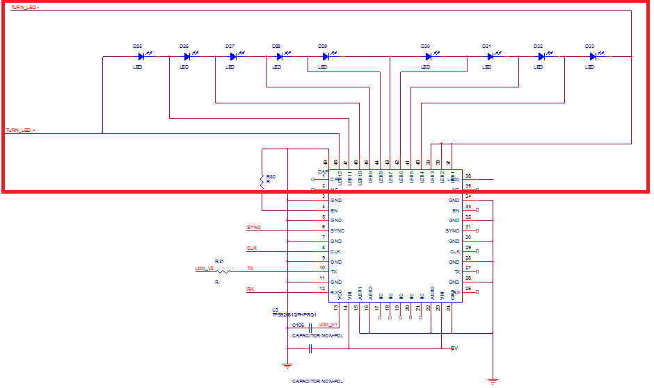
I am currently developing a car lamp.(TURN signal)
Here are two questions:
1. When using the buck-boost circuit, can LED0 ~ LED4 of TPS92661 be connected to LED- instead of GND?
2. possible to control using UART communication by changing to PIC?
Hello,
I'm working on finding the right person to answer your questions. I will let you know as soon as I can. Thanks.
Regards,
Clint
Hello,
I have some answers from the experts on this device:
1. Yes, LED 0 through LED 4 can be connected to LED-.
2. Yes as long as the PIC chosen is UART compatible, correct for your design, and has enough bandwidth.
I do have one thing to mention and that is a concern using a buck-boost regulator with this device. It can be done but it depends on a lot of factors and you have to be careful. The ideal solution is to drive the LED string/TPS92661 with a buck regulator. They have continuous output current so the devices we commonly use with this IC are the LM3409 and TPS92515 since they do not need any output capacitance. A buck-boost does require some amount of output capacitance so shunting LEDs will cause some serious transients and could even blow the switches (all that capacitor energy needs to discharge somewhere when the string voltage drops). The most common way this IC is utilized is using a boost voltage regulator followed by the LM3409 or TPS92515. That will give you the best performance. But like I said, it can be done with buck-boost and it really depends on your application and exactly how you are implementing it, but I'm just warning you of potential problems.
Regards,
Clint
Hello,
I think that would be fine if the same number of switches in the TPS92661 are on/off each cycle. But it could be an issue if not. The output capacitor will be charged to whatever string voltage you have. If you have a 30V output one cycle and then shunt some FETs so it is only 20V the next cycle that 10V of energy will discharge through the FETs and LEDs that are on. You could have high peak currents.
What is the actual use for the TPS92661 in this application? Do you need to dynamically switch the number of LEDs either when the LM3423 is on or off? Thanks.
Regards,
Clint
Hello BJ,
If you are typically increasing the LED string during the on time then it is just a matter of loop response and it should be fine. Decreasing is where you would have the issue. Perhaps even at the next turn on even if only increasing while on.
If it is only increasing you may want to not use the disconnect FET so that the cap can discharge more before the next on cycle. In that case you can just dim only between cycles and leave the device running while the matrix increases the LED number.
If you are decreasing at any point during the on time you could cause damage due to the buck-boost output capacitance. That is where a buck that does not need output capacitance solves the issue.
Regards,
Clint
Hi Clint,
Thank you for your attention and support.
I decided to change the development concept.
Is it possible?
-. Boost -> Buck(LM3409) -> LED Driver(TPS92661)
Please recommend the following products.
-. Boost Spec
1. Input : 8 ~ 26Vdc (Typ 13.5Vdc)
2. Output : 42Vdc / 300mA
Hello BJ,
A couple commonly used devices for the boost stage that come in Q grade are the LM5122 and the TPS40210.
Regards,
Clint