This thread has been locked.

If you have a related question, please click the "Ask a related question" button in the top right corner. The newly created question will be automatically linked to this question.

UCC28063A: How to improve phasing between GATE A and GATE B

Part Number: UCC28063A
Other Parts Discussed in Thread: UCC28063, LM5112

Hello all,

What are some things to look for, to improve the phase relationship between Phase A and Phase B? 

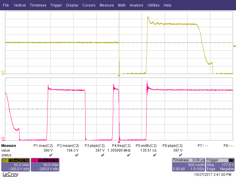
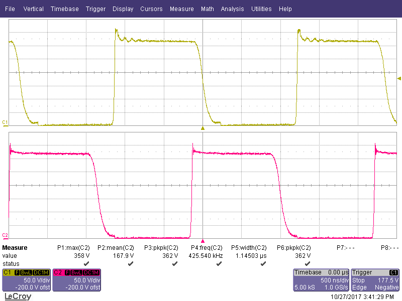
Right now I'm getting about a 100 ns error. The on-times are identical, and ditto the signals on ZCDA and ZCDB.

TIA

  • interleave_control.pdfHi Jason,

    There will be some difference between the two phases of the interleaved power stages due to the tolerance of the components so it is normal to see some difference between the two phases.

    I have attached a paper on the Natural Interleaving control used in the UCC28063 which explains the concept in more detail.

    Regards

    Peter

  • Thanks for the paper. However it does not address the issue of the 2 channels not being 180* out of phase. I'm seeing an error.. maybe 160*.

    Is there something in the layout or design that could cause a phase error?

  • Hi Jason,

    Have you measured the inductance of the PFC chokes in two phases to see what level of imbalance there is between them? In the meantime I will ask my colleagues if they have seen similar issues before.

    Is there a particular operating condition that the phase shift is 160deg's, does it ever achieve 180deg?

    Regards

    Peter
  • I first tested with 2 inductors at low voltage (~200 Vo): 86 uH and 89 uH.

    Then I replaced them with another 2 inductors, and actual voltage (320 Vo): 64.1 uH and 64.4 uH. It got worse.

    See 3 different waveforms below, at 3 different random combinations of load and input voltage (always below 30% load). 
    The first one shows malfunctioning.


  • Oh and sometimes they sit there in-phase.

    I did a test where it was in phase vs. out of phase (maybe 160*). 2 different conditions.

    I measured the GDA and GDB widths, by measuring the time from where the waveform just begins to rise, to where it just begins to fall:

    in-phase condition:

    GDA  547 ns

    GDB  551 ns

    (GDB is 0.7% wider)

    out of phase condition:

    GDA 1.441 us

    GDB 1. 439 us

    (GDA is 0.1%  wider)

    That's a change of 0.8%.

    Looking at Fig 11 of the datasheet, it looks like 30* of change in phase should produce a 2% change in on-time. (Rtset = 66 kΩ)

    Above I'm only getting 0.8% of change with about 160* of change in phase.

    I am using the LM5112 gate drivers to drive my FETs, and I double checked the differential error in on times and it is only 7 ns. (i.e. if driven with identical on times, their outputs' on-times are different by 7 ns)
    What gives?

    Fig 11: