This thread has been locked.

If you have a related question, please click the "Ask a related question" button in the top right corner. The newly created question will be automatically linked to this question.

LM2577: Compensation capacitor failure

Part Number: LM2577

Hi,

the current flyback design used LM2577 to boost +5V input to +15V (75mA) & -15V(110mA). 

We using Cout - 330uF,50V

Cc - 330nF, 50V, X7R, 20%, 1812 package

Rc - 3.01K,1% 0805 package

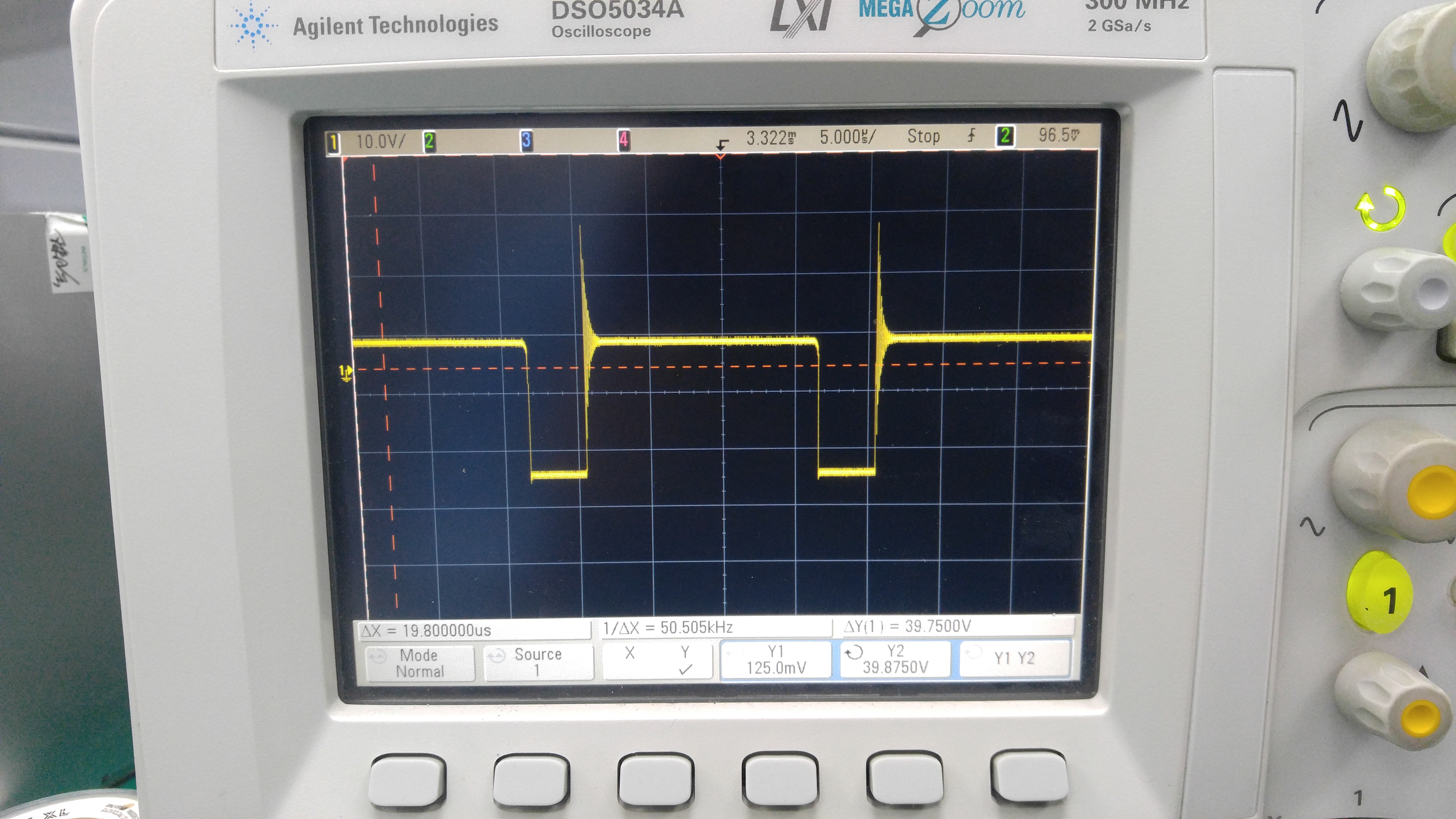
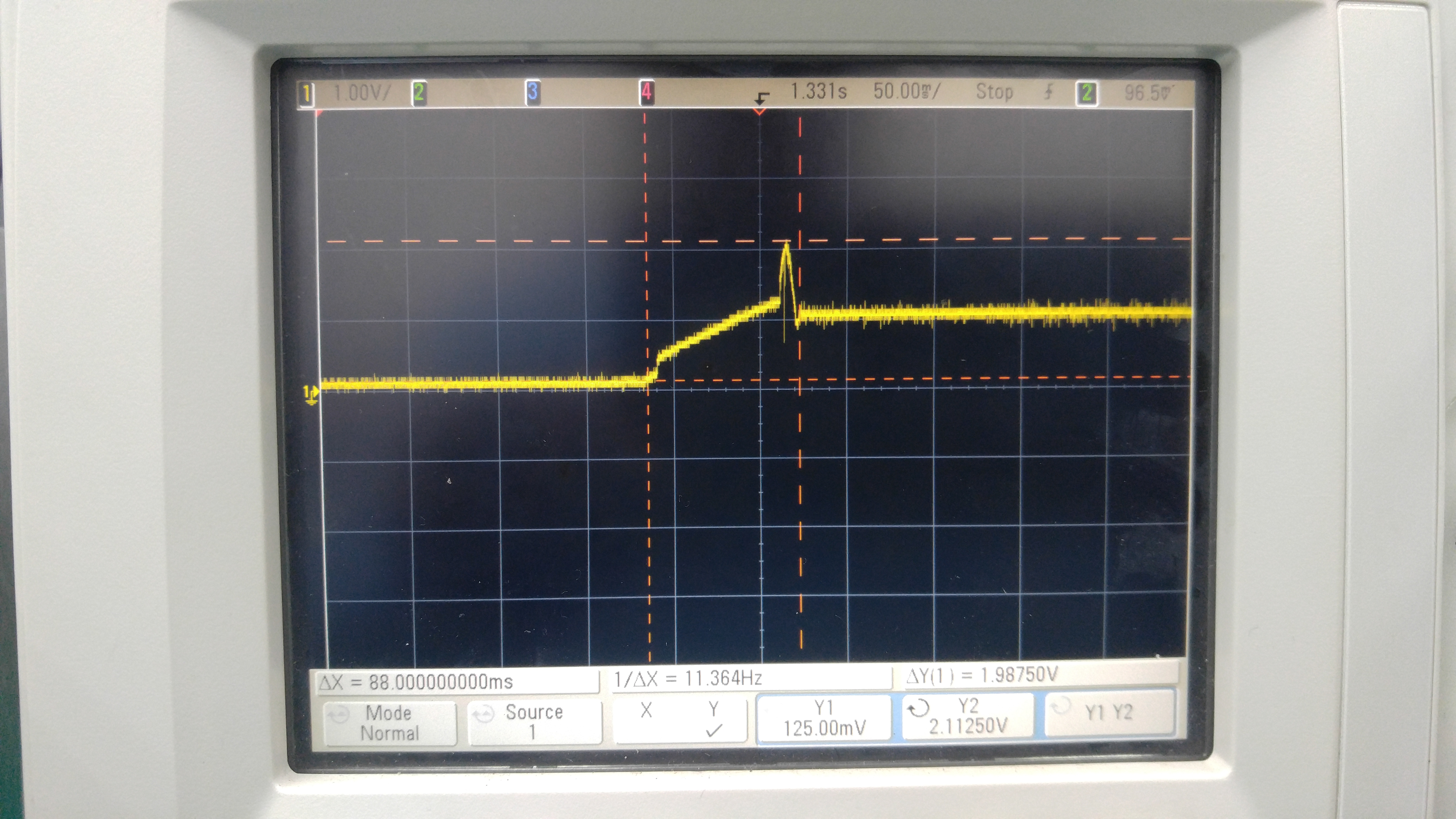
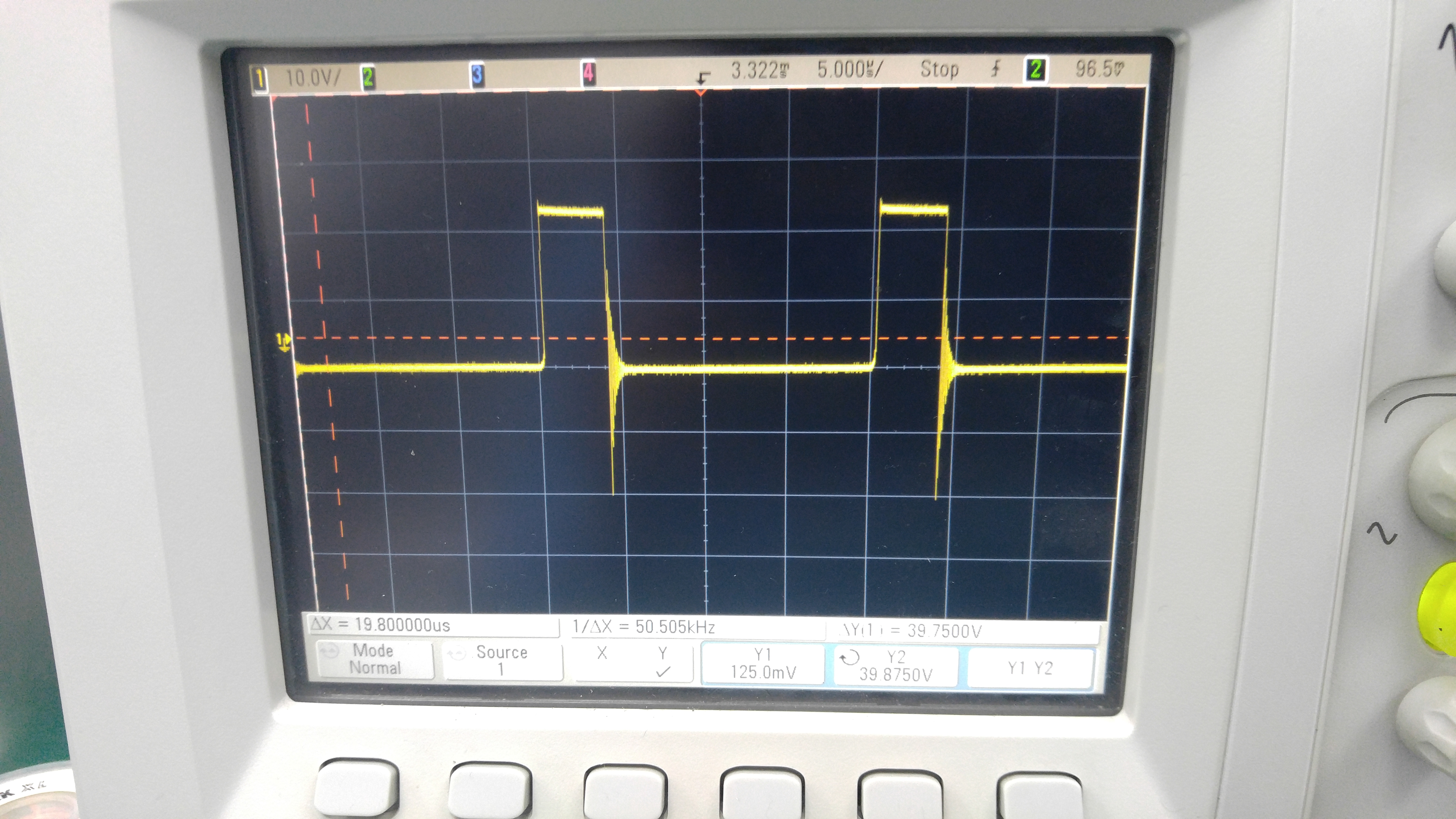
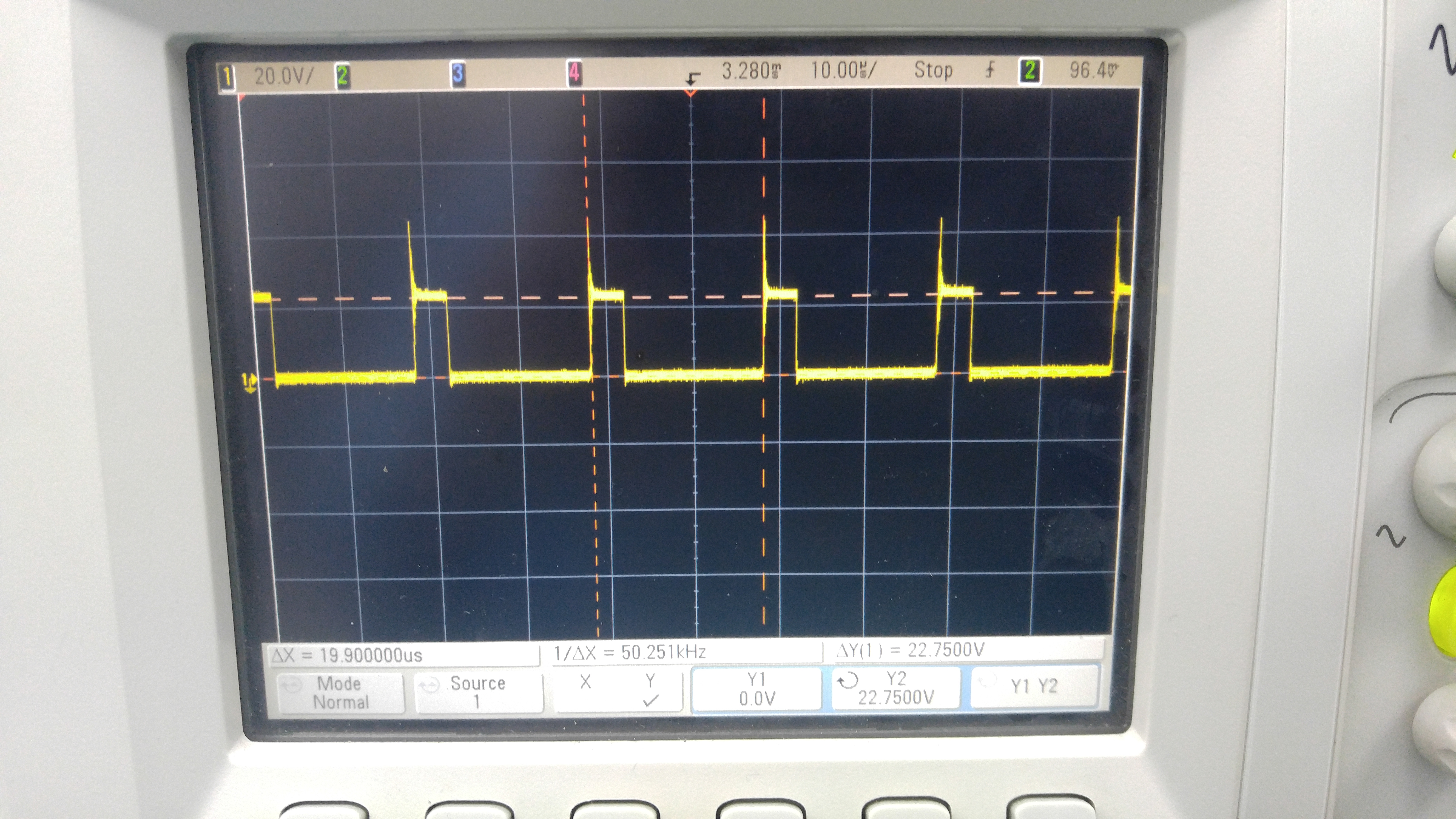
It runs at 50KHz freq. Ripple measure @ load - 200mV P-P

We are facing 2% of compensation capacitor failure during functional test. i.e- Capacitance dielectric fails and IR measure in Ohms instead of Mohms.

Can you please comment what can cause compensation cap failure ?

  • Hi,

    Can you show me the layout and schematic?
    And also please show the waveform on Comp pin and Vo.

    Best Regards,
    Zack
  • Hi Zack,

    Thanks for your response.

    Word document attached for your reference.

    LM2577_TI.docx

  • Hi Natarajan,

    Can you give me the zoomed waveform because I cannot see clearly from the work document.
    And have you ever tried to replace new capacitor to the failure board? Did the chip also stop working after changing new capacitor?
    Form the layout in the document, it seems that the layout is not so good. Keep SW pins close to transform to decrease the leakage inductance so that the spikes on SW will much smaller.

    Best Regards,
    Zack Liu
  • Hi Zack,

    sorry for late reply.

    Waveforms attached for your reference. Yes, after we replace new capacitor, our PCBA start functioning. what we observed is microcrack in the capacitor after the functional failure ( during fuctional its failing ). will the capacitor generate microcrack due to spikes on SW ? OR anyother electrical parameter cause this microcrack ?

    For your info. we verified all our process ( from SMT to Assy ), there is no crack generated in our process. PCBA fails only at functional test.

  • Hi Natarajan,

    According to your reply, I think the microcrack on this capacitor is due to the mechanical stress. If the capacitor fails because of the high voltage, the chip will not work after changing a new capacitor.
    I suggest you have a new layout because now the transformer is far away from the chip. The high leakage inductance will cause high spike on SW pins and also cause high temperature rising on transformer and the chip. The high temperature will let the board have deformation.

    You can also have a try to use other kinds of capacitor.

    Best regards,
    Zack
  • Thanks Zack,

     We measured the temp rise on transformer, LM2577 and capacitor. The maximum temperature rise observed 34 deg celcius ( room temp 21 deg Celcius ).

     We parallely working on to use Soft termination capacitor in the circuit.

     I just want to know, other than the layout issue, process issue, what else can cause this microcrack electrically ?

    > Component reliability ?

    > Any electrical surges ?

    > ESD ?

    > transient response ?

    > any other ?

    Need your advice. Thanks

    Natarajan


  • Hi Natarajan,

    Usually the microcrack on capacitor is caused by mechanical stress. Failure of ceramic capacitors due to PCB flexure is a common problem.
    Have you ever test the transient response or other electrical test?

    Best Regards,
    Zack
  • Thanks Zack,

    As a product we did this test but not as a PCBA level.

    Now we focusting on getting soft termination capacitor to resolve this issue..

    thanks for your support.