This thread has been locked.

If you have a related question, please click the "Ask a related question" button in the top right corner. The newly created question will be automatically linked to this question.

TPS54325: Could you tell me about how to select TPS54325's inductor's value?

Part Number: TPS54325

Hi, team.

I have previously contacted the following inquiries.

e2e.ti.com/.../648546

I understand the features of D-CAP2 to a certain extent, but please let me know about question.

Could you help me?

<Question>

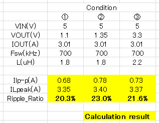
My customer is studying the design with the following voltage and inductance value, is it usable?

① 5.0 V ⇒ 1.1 V:1.8 u H

② 5.0V ⇒ 1.35V:1.8uH

③ 5.0 V ⇒ 3.3 V:2.2 u H

We will also list the parts selection table of TPS54325 for reference.

(Customers want to select from inductors used in the past, but they are in trouble because they can not choose the one with the value as per the table.)

Best regards,

Pokkun (Masumi Sekiguchi)

~~~~~~~~~~~~~~~~~~~~~~~~~~~~~~~~~~~~~~~~~~~~~~~~~~~~~~~~~~~~~~~

<Background>

Q1: With the same sense as in current mode and voltage mode products, customers have said that they want to know the phase margin of this product.

A1: I explained that because the D-CAP2 product is in hysteresis mode, I do not have to think about the concept of phase margin.

Q2: Then, the customer asked "How mean of stable output?"

A2: I replied that it is the feature of this product that it stabilizes if peripheral components are selected according to the specified table (Table 2).

Q3: Then I asked you to confirm that I can not choose an inductor as per the table, so I asked you a question.

~~~~~~~~~~~~~~~~~~~~~~~~~~~~~~~~~~~~~~~~~~~~~~~~~~~~~~~~~~~~~~~

  • You can use 30% to 40% inductor ripple to calculate L.
  • Previously, from the customers there was a question that manual calculation would not result in the L value as shown in Table. (In hand calculation, the inductance changes depending on the load current, so it became a situation that it is not known whether it can be used with a fixed value.)

    So, the inductance value fixed by the table should have a range, but can you tell me the range?
    If it is impossible to indicate the range, please tell me whether to output stable with the sent constant.

    If can't answer it, I want that you check with the engineer who gave the answer at the time of the previous post.

    Please help me!
  • Hi.

    How about this matter?
  • 1.The L value as shown in Table can't cover all the VIN,VOUT cases. You can use 30% to 40% inductor ripple to calculate L.
    2.You can use 30% to 40% inductor ripple to calculate L. 30% to 40% inductor ripple this is the range.
    3. L & C are both related to stable states, not just L.

    Yes, if you want, you can check with the engineer who gave the answer at the time of the previous post.
  • Thanks for the reply.
    Can you confirm questions below to the engineer who gave the answer before?

    <Question>
    My customer is studying the design with the following voltage and inductance value, is it usable?

    ① 5.0 V ⇒ 1.1 V:1.8 uH
    ② 5.0V ⇒ 1.35V:1.8 uH
    ③ 5.0 V ⇒ 3.3 V:2.2 uH

    Best regards,

    Pokkun(Masumi Sekiguchi)

  • It is OK. Pls be careful that "L & C are both related to stable states, not just L".
  • Thank you !

    >Pls be careful that "L & C are both related to stable states, not just L".
    ⇒Roger this !

     So, if questioning inductance can be used, I'll be happy if you can tell me the corresponding capacitance too.
  • You can refer the reference range value written in the datasheet.
  • Thank you for your answer.

    When calculating by referring to the data sheet description or calculation formula, L changes according to the load current.

    Since this product is a maximum load 3A product, when designing it up to 3A load, the L value at light load is different value.
    L value of "D-CAP2" product is fixedly described in the table, it differs from its own calculated value.

    For this reason, I was inquiring to you the case of inductance deviating from the data sheet table.

    I know that the calculated value and the target ripple rate are described in the data sheet, but it does not match the calculated value from the background, or it becomes confused by becoming L value more than 10 times depending on the load.

    Could you check with the engineer if it can be used with the above inductance or not?

    Can you ask "Jason Wang-san" or "Vental Mao-san"?

    Please help me !

  • 1. L changes only when load current is close to saturated current.
    2. The L value at light load is fixed.
    3. L value of "D-CAP2" product is not fixed.
    4. The case of inductance deviating from the data sheet table is the typical inductance for typical customer application spec.
    5. What's your " background"?
    6. What is your meaning of "becoming L value more than 10 times depending on the load"?
    7. You can check with the engineer in the previous post.

    By the way, if you doesn't believe any theory and any sentence. Pls do experiment to check the sentence. Change the L. Change the C in the actual experiment.   

  • ~~~~~~~~~~~~~~~~~~~~~~~~~~~~~~~~~~~~~~~~~~~~~~~~~~~~~~~~~~~~~~~

    <Background>

    Q1: With the same sense as in current mode and voltage mode products, customers have said that they want to know the phase margin of this product.

    A1: I explained that because the D-CAP2 product is in hysteresis mode, I do not have to think about the concept of phase margin.

    Q2: Then, the customer asked "How mean of stable output?"

    A2: I replied that it is the feature of this product that it stabilizes if peripheral components are selected according to the specified table (Table 2).

    Q3: Then I asked you to confirm that I can not choose an inductor as per the table, so I asked you a question.

    ~~~~~~~~~~~~~~~~~~~~~~~~~~~~~~~~~~~~~~~~~~~~~~~~~~~~~~~~~~~~~~~

    The following is the result I calculated.


    The ripple rate is "20.3%, 23.0%, 21.6%", but is this inductance usable? (YES? Or NO?)

    ① When it can be used (The answer is "YES".)
    How many Output and Feed Forward Capacitors (C4, C8 + C9) can be used?

    ② If you can not use it (The answer is "NO".)
    Will not the inductance be fixed by the condition?

  • 1. D-CAP2 must meet phase margin requirements. That's why LC written in the datasheet has some reference value.

    2. It is not the feature of this product. The LC table in the datasheet is the ref data based on the loop analysis.

    3. Yes. You can use that inductor. 22uF to 68uF is cap range.