This thread has been locked.

If you have a related question, please click the "Ask a related question" button in the top right corner. The newly created question will be automatically linked to this question.

LM5160A: Flybuck EMI issue

Part Number: LM5160A
Other Parts Discussed in Thread: LM5160, LM5160DNTFBKEVM, PMP10532, PMP

Hello,

I'm using an LM5160 for a two output isolated flybuck. It is converting from 10-40 Vin to 3.3 Vout for all outputs (the isolated and non isolated one). It is working very well, except for EMI which is not very good (out of class B). Even with filtering, is not easy to achieve low EMI in conducted emission (150 KHz - 30 MHz).

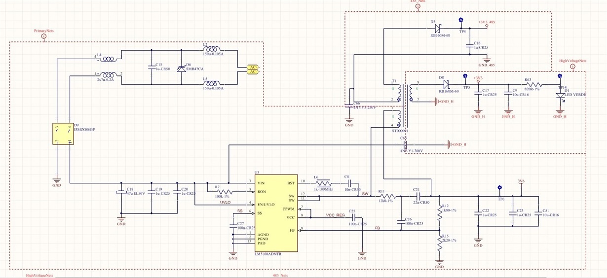
Here below my schematic, where transformer has an inductance of 8 uH.

Did you test the LM5160DNTFBKEVM for conducted emission? Is it possible to have their data? Do you have any idea on what to do to reduce emi?

Thank you,

Mattia Berton

  • Hello Mattia,

    I will check and see if we have any EMI data to share? I took a look at your schematic and I noticed that you have a bead in series with Cboot, suggest placing a 5 ohm resistor. Also suggest placing an RC snubber from Vswitch Primary to Gnd. Suggest a value of 1ohm and 100pF and increase 100pF up to ~1nf to help EMI profile. Looks like you will probably need an input CM Filter too, as the CM noise is likely your issue above 1MHz, certainly above 10MHz.


    Hope this helps?
  • PMP10532_Fly-BuckConductedEMI data.pptxplease see attached results for PMP10532.  The PMP schematic can be viewed online, the filter was added to the schematic at the input.  The values used are called out in the attachment. Please note, that input would be on the left (LISN) and output (LM5160) on the right.  implement a Pi filter with Cf on the Left side of Lf and Cd on the right side.  Please make sure Cd has an ESR>200mR to provide adequate damping.

    Hope this helps?

  • Hello David,

    I followed your guidelines, but what I obtain is to move noise from one domain to another (in my case, from the power input to the RS485 zone). It seems as if the topology is very noisy, even if very low part count. Of course, if I use a very large input filter I can reduce my EMC noise, but the source is still present. What I'd like to do was to reduce the noise sources in any way.

    Thank you for your support. What do you think is the best stack layer for the transformer?

  • Hello Mattia,

    For the Transformer stack, I suggest the following.

    The Primary should "sandwich" the secondary's. By this, I mean, winding half the primary first, then insert the secondary's and then finish off the second half of the primary. I would place the Vsw Side of the primary on the inner most part of the of the bobbin, closest to the core (i.e. start with Vsw Side of Pri) so that the following turns shield Vswitch node of the transformer.

    Hope this helps?

    David.