This thread has been locked.

If you have a related question, please click the "Ask a related question" button in the top right corner. The newly created question will be automatically linked to this question.

LM5140-Q1: The switch node jitter

Part Number: LM5140-Q1

Hi,

We got a question from the customer about LM5140-Q1.
Could you help us?

[Question]
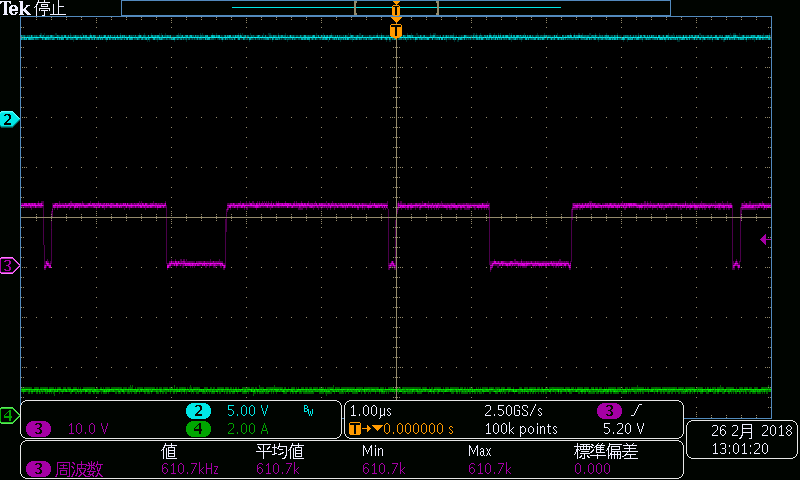
They are evaluating LM5140EVM and found big switch node jitter. Please refer to attached file.

LM5140Q1 test result_Feb2618.pptx

- Case 1 -
 Condition: EVM default setting(2.2MHz operation)
 Phenomenon: The switch node jitter of Vout2(5Vout) is bigger than Vout1(3.3Vout).

- Case 2 -
 Condition: 440kHz operation; they changed the value of external components. please refer to attached file
 Phenomenon: The switch node jitter of Vout2(8Vout) is bigger than Vout1(3.3Vout).

They assume the jitter becomes big as output voltage setting is rised. They have questions about this phenomenon.

- Why does the jitter become big as output voltage setting is rised?
- Are there any solutions for this phenomenon?

Best Regards,
tateo

  • Tateo,
    Thank you for your question about the LM5140-Q1 jitter. Are you making the measurements on the standard or the High Density EVM? For a buck controller there will always be some amount of jitter on the switch node. The LM5140 jitter is less than 8%, so the case 1 waveforms look normal.
    It does looking line the scope leads used to make the measuring are long (ringing on the leading edge of the waveform) which may add some noise to the measurement.
    For case 2, are you in DEMB, or FPWM mode?
    Terry
  • Hi, Thank you for your quick reply. They measured on standard EVM. For case 2, they measured at both of mode. Please refer to attached file in previous post.

    Best Regards,
    tateo

  • Hi, Is there any update on that? We would appreciate it if you could give us your feedback.

    Best Regards,

    tateo

  • Tateo,

    Sorry for the delay responding to your question about the LM5140 jitter. As I mentioned for case 1 the jitter looks normal, you could try increasing the VDDA capacitor from 0.1uF to 1uF to see if this helps.


    For case 2 I recommend that you change R18 from 22k to 8.2k, and C7 from 47pF to 22pF. I would also try increasing the VDDA capacitor from 0.1uF to 1uF.

    Terry

  • Hi, Thank you for your support. They tried your suggestion of case 2 and they could reduce the jitter. But the unstable sw-node is still occurred at 1A load in DEMB mode. And we got additonal questions.

    - What is the cause of SW-node jitter?
    - Is there any solution to fix the unstable SW-node at 1A in DEMB mode?

    Best Regards,
    tateo

  • Tateo,

    With a 1A load the LM5140-Q1 maybe transitioning from DCM to CCM. The way to debug this is to place the LM5140 in FPWM.  If the SW node waveform appears normal, it is not instability, it’s the transitions from DCM to FPWM.

    Terry

  • Hi, Thank you for your reply. They checked more detail of DEMB behavior on 8V output. Please refer to attached file. We got additional questions.

    LM5140Q1 DEM test result_15Mar18.pptx

    - In DEMB opeation, the gate short pulse of low side FET is occurred. What is the cause of this phenomenon?
    - What is the condition of entering PFM mode? They assume that the condition is into DCM mode. However the IC is operating PFM mode in spite of CCM mode.

    Best Regards,
    tateo

  • Tateo,


    Sorry I’m not sure I understand. Is the DEMB pin connected to AGND, or VDDA? 

    The perceived instability is a result of the controller transitioning between 2 operating modes when DEMB=0V.  With light loads, we enforce a minimum amount of energy per SW cycle to encourage the controller to overcharge the output allowing sleep and low IQ.  At higher loads, normal COMP controlled duty cycle control takes over.  This region can be avoided by keeping the load above 20% of the programmed ILIM or as you observed taking DEMB=5V.  

    When the LM5140 is in DEMB mode, and there is a light load on the output the LM5140 will go into standby mode when:

    • FB>VREF

    • COMP<300mV

    • No HO pulses for 16 consecutive CLK cycles.

    •  

    AS the load is increased the LM5140 will come out of standby mode when:

    • FB<0.99*VREF.

    Terry

  • Hi, Thank you for your reply. They checked it at DEMB mode(DEMB pin is connected to AGND).

    They comparaed the waveform between 3.3V output and 8V output. Please refer to attached file in previous post. 3.3V output seems normal PFM behavior which the switching frequency increase as the load increases and there is not the short pulse on LO pin. They are concerned whether the behavior of 8V output is unstable. Could you please check why the short pulse is occurred?

    By the way, we got LP5140EVMHD. We are going to check the behavior on this board, too.

    Best Regards,
    tateo

  • Tateo,

    I understand your concern, but based on all the testing I have done, I sure that the waveforms are normal. 

    Terry