Other Parts Discussed in Thread: BQPRODUCTION, BQMTESTER
Hi, I've been trying to voltage calibrate and current calibrate my 3 cell battery pack which uses the bq40z60 IC and i have a few problems I could use help with
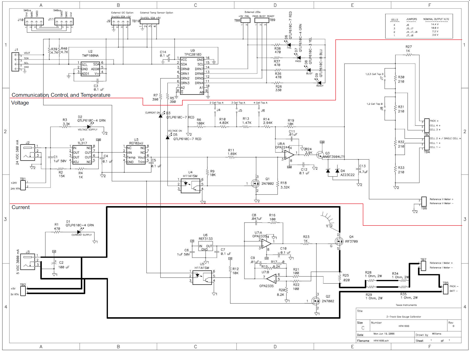
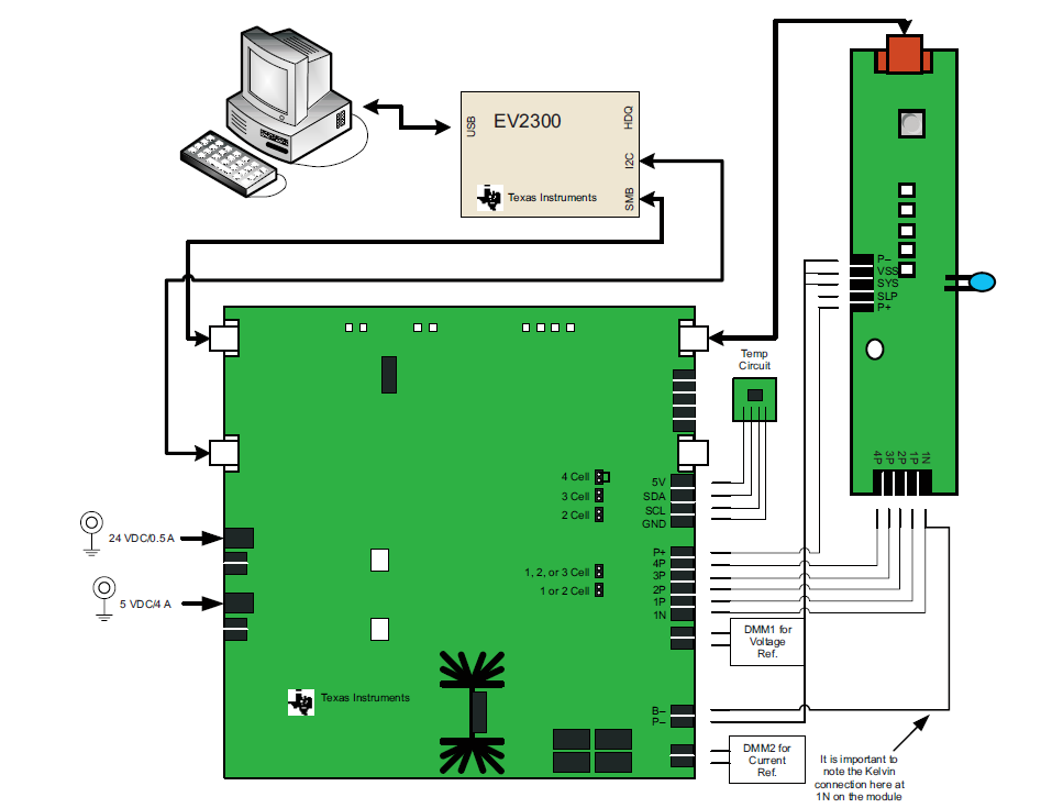
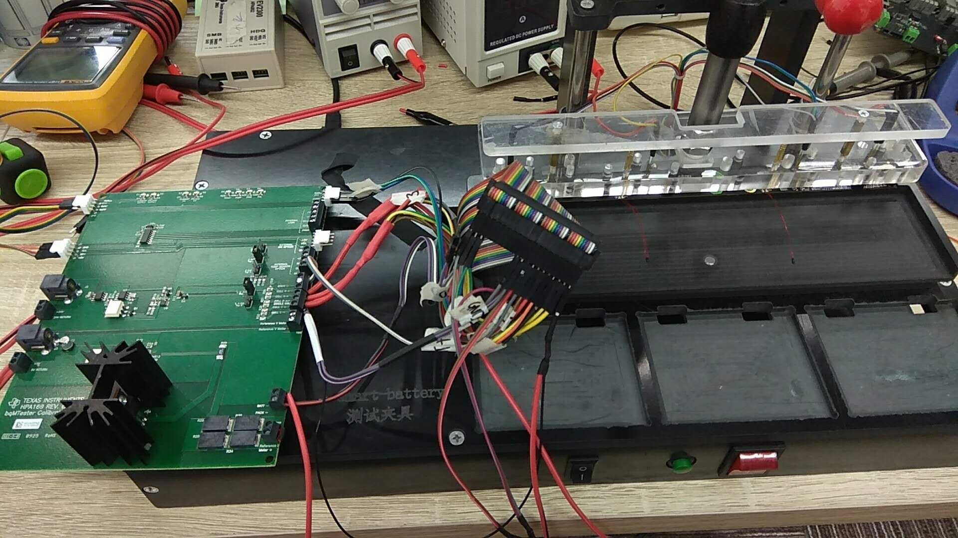
I have the HPA169 connected to my Device Under Test. I'm aware that the DUT should be able to be powered from the 20V on the HPA169 however without connecting my 18V PSU, I get a "no device acknowledge" error in bqProduction even though PACK+ of the DUT is connected to the PACK+ terminal of the HPA169. I've followed the connection diagrams as shown by "sluu238b - bqMtester User Guide"
Secondly, I want to have a system where a user can use bqProduction to program and calibrate the DUTs whilst only inputting calibration values once a day, this is relatively simple however i seem to get a larger margin of error for PACK CURRENT: when discharging the battery across a load, the current has a 3% margin of error. I am aware of the Kelvin connection necessary for the "1N-" connection and have made connections accordingly.
Lastly, i also want to include a way of testing the charging and discharging function of the DUT as this is the first test after the PCB Assembly of the DUT, is there another program or another function of bqProduction which would allow simple charge and discharge function of a DUT?
To summarise
- Cannot use the 20V supply from the HPA169 to power my DUT
- 3% margin of error after calibrating using bqProduction
- Would like to charge and discharge test my DUTs after testing with bqProduction