This thread has been locked.
If you have a related question, please click the "Ask a related question" button in the top right corner. The newly created question will be automatically linked to this question.
Hi all;
I've an overheat problem with LM2586 and power inductor.
PURPOSE
I designed a constant current source for driving 60V-LED-bars with 12-24 VDC. The required input voltage range is 9-36 VDC, the nominal LED bar voltage is 54-57 VDC and drive current is around 200mA.
PROBLEM
The circuit works as expected and the temperature levels seems normal at the first 30-minute-operation. But after nearly half an hour, the power inductor starts to buzz, overheats then fails permanently.
WHAT I TRIED
At first I thought that the problem comes from the DC resistance of the inductor, so I've replaced it with WE 7447709681 since this one has lower DC resistance. But the problem repeats. I also put a 22k resistor across the FREQ ADJ pin to increase the switching frequency, but didn't help.
Here's the schematic:
NOTES:
- BL pin comes from an MCU to turn on and off the lights.
- There's a pi filter (100uF-68uH-100uF) before the input, VX. But it's in another sheet, so I couldn't show it here.
Here's the PCB:
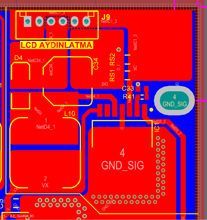
What can you suggest?
Thanks in advance.
Zack Liu said:Hi Rohat,
1. The input voltage range is 9-36V, Output voltage is 60V@0.2mA, right? When input voltage is 9V, the input current needs to be 1.48A(Efficiency assumed to be 0.9). The two inductors you choosed has a too small rated current. Please choose a higher rated current inductor.
2. Add a 0.1uF bypass capacitor closed to vin pin.
3. VX wire width is too small at the left bottom corner. And also add the copper area around inductor for heat dissipation. How does the C34 ground connect to the bottom ground plane? Add vias if needed.
Regards,
Zack
Hello Zack,
Thanks for your answer.
1- The output current is 0.2A and the output voltage varies with the load but it's 54 VDC maximum. Nominal input voltage is 24 VDC during our tests and the inductor failed under this condition. About the inductor, unfortunately I cannot due to size limitation (7x7mm). Also, WE's inductor has the lowest RDC, so I have to use it.
2- 100n ceramic capacitor is under L10 (bottom left). But I'll move it close to the 7th pin.
3- Track thickness is 1mm at the bottom-left (VX) and 0.65mm to the VIN pin. Could it be the issue? You're right about the copper area for the inductor, but unfortunately there's no chance to put it due to the size limitation. C34 connects to the bottom GND plane through a 0.6mm-via near RS2 by the way.
The strange thing is that the problem shows itself about 30 minutes after powering up. When we test the same circuit with another load (49 VDC output voltage with the same load current), it works with no problems.