This thread has been locked.
If you have a related question, please click the "Ask a related question" button in the top right corner. The newly created question will be automatically linked to this question.
Pasting this in from the prior thread
I cant access the questions on the schematic. Perhaps you can post them in another way.
Your timing diagram was very helpful. Hopefully, TI will include it in a future rev of the 72295 datasheet
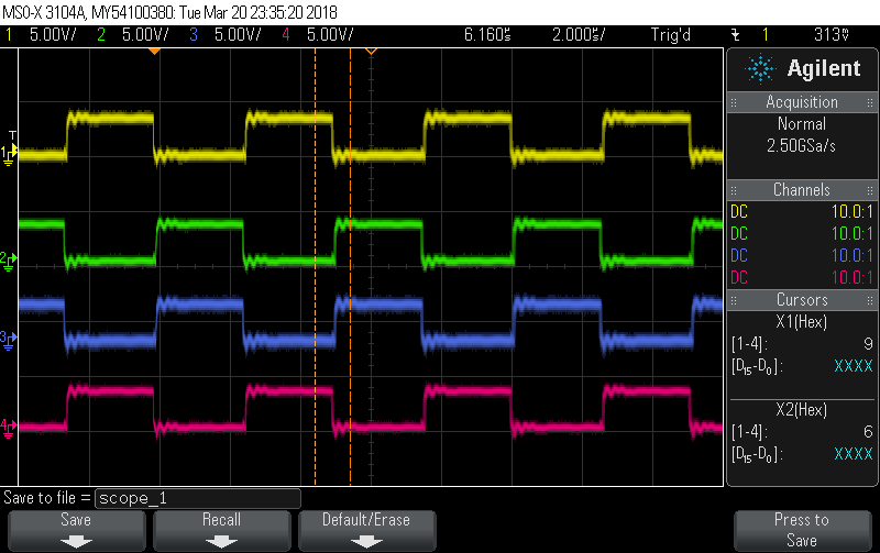
I attached scope shots of the LI and HI signals I now have. Going from top to bottom... HIA, LIA, HIB, LIB.
The top shot is a 50% duty cycle, the bottom is 80%.
The ringing in the traces is due to less-than-ideal scope probe grounding,
Hi Nicholas,
Thanks for the update. It doesnt look like HOA/HOB are 180deg separated and not completely interleaved for 2 phase. I went ahead and included the schematic review in a screenshot below. I also put the SM72295EVM on the bench and verified that powercycling VCC with VDD still present does not affect the part while not switching. While switching the HO/LO output behave as expected from HB-HS UVLO having HO shut off before LO due to the lower threshold. As we Discussed, either we can create a new thread or I can post in this one about minimum bootstrap charge time and deadtime input Jef feasibility for this application. If we dont post a new thread I will simply reply back to this thread within 24-48 hrs.
Thanks,
Jeff
Thanks, Jeff
>>If you need support designing in the current sense amps, feel free to reach out again<<
The layout is optimized to use the INA213 so we will likely stick with them. They also have very good input offset voltage spec.
>>For the deadtime - its still recommended to not shape the input signal and if you do make sure the signal is not over shaped as to not be attempting a large deadtime.<<
We find that we are getting much better results when we remove the capacitors (C23 - C26) from the input signals. I think that those RC networks, in conjunction with the programmable dead time I am able to introduce between the complementary signals, was hurting us. I still have a minute amount of dead time programmed in that is producing about 100nS of deadtime between HI and LI. What I originally though was a deadtime issue was apparently an issue of an excessively high DC on the lower MOSFETS (as we discussed), which also causes shorting issues. I am planning to leave in the 270 ohm resistors though (R28 - R31) as these probably help to preserve signal integrity / decrease ringing.
>>. I have contacted the designer for this TIDA and hope to update you with an answer asap focusing on if this deadtime approach should be done, and with 270 ohms.<<
It would be interesting to see what he / she has to say about this. Since I can control my deadtime through software this is probably sufficient. I wish I could control phase between the timer channels as easily! I have a question in to ST about that.
>>Did your other concern have more to do with minimum ON time of LO in order to recharge the bootstrap?
or maximum ON time of HO to deplete the bootstrap below HB-HS UVLO or your systems required HB ripple?<<
My big concern here is how to determine the minimum on time of LO to recharge the bootstrap cap. (or, to look at it another way, how to determine the maximum ON time of LO before shorting occurs from V_OUT to GND through the LO MOSFET and inductor) I've sort of determined this empirically but I would like to understand it better from a theoretical standpoint.
Hi Nicholas,
Just checking to see if you had any more questions or concerns with SM72295?
If not, and this thread was resolved to your satisfaction, please click the green button.
Thanks!