This thread has been locked.

If you have a related question, please click the "Ask a related question" button in the top right corner. The newly created question will be automatically linked to this question.

TPS40400: TPS40400 Output Current Reporting Issue

Part Number: TPS40400

Hi  

I had one question about the output current report problem (not accurate) with the TPS40400.

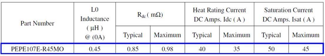
The test board is TPS40400EVM-351, therefore the current sense element is the inductor’s DCR.

Please refer the inductor spec as below table.

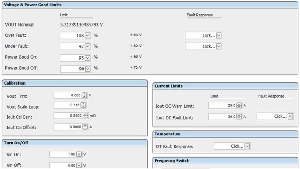
The below table is my configuration and test result.

  1. The setup value on “Fusion Digital Power Designer”.
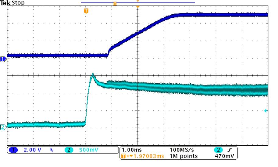
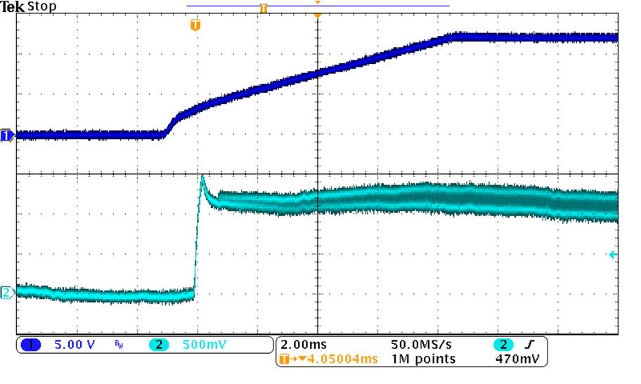
2. The test result

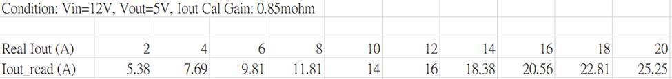
Would someone help to give us some suggestions that would get more accurate output current through PMbus?

  • Hi,
    Please change Vout scale loop to 0.12 . what is your operating frequency? You may be having too high ripple current at light loads. also check the RC filter across the inductor for the current sensing meets datasheet criteria.

    Regards,
    Mathew
  • hi Mathew,

    Thanks so much for your great support.

    I would adjust the different R5-C4 time constant to make the output current reported correct value at Vout=1.2V and 5V separately.

    However, the same R5-C4 value would not satisfy Vout=1.2V and 5V.

    I will try different inductor to meet all operating condition.

    By the way, I have another question about the VTRACK function.

    In order to get the linear scale voltage follow behavior, I took off the R13 from the EVM.

    However, the output voltage will not regulate at the set-point voltage.

    It seems the Track pin would not  floating and need be connected to internal LDO.

    I also measured competitor’s product (with TPS40401) as below.

    1.      Condition: Vin=12V, Vout=5V; CH1: VOUT, CH2: VTRACK (Do not use track function)

    2.      Condition: Vin=12V, Vout=5V; CH1: VIN, CH2: VTRACK (Do not use track function)

    3.    Condition: Vin=12V, Vout=5V; CH2: VTRACK (Do not use track function)

    It shows the VTRACK voltage has one 600kHz (the same as switching frequency) square wave and it would make the controller work good while it use voltage track function or not.

    Would you kindly to guide me how to use the voltage track function well?

  • Hi,

    If the Vtrack function is not used the pin needs to be tied to BP3. it is intended to be used if you want the output to track an external voltage on turning by mimicking the rise time of the external voltage the output of the TPS40400 needs to track. If this is the case you would create a resistor divider to that external voltage and connect the track pin to the middle of the divider.

    Yes I would expect the RC values to be different for the 1.2V and 5V outputs as the inductor values,dcr and output voltages are different.

    Regards,

    Mathew