Because of the holidays, TI E2E™ design support forum responses will be delayed from Dec. 25 through Jan. 2. Thank you for your patience.

This thread has been locked.

If you have a related question, please click the "Ask a related question" button in the top right corner. The newly created question will be automatically linked to this question.

TPS25923: Heavily fluctuating power through eFuse configuration

Part Number: TPS25923

Hello all,

I'm having major issues with the TPS25923 in a simple, no external MOSFET configuration, for the purposes of protecting an ADC circuit's power input.

I take in 5V and run it through the eFuse out to the TPS6209733 3.3V power regulator, and at first was getting no power through the fuse at all. Below is my schematic.

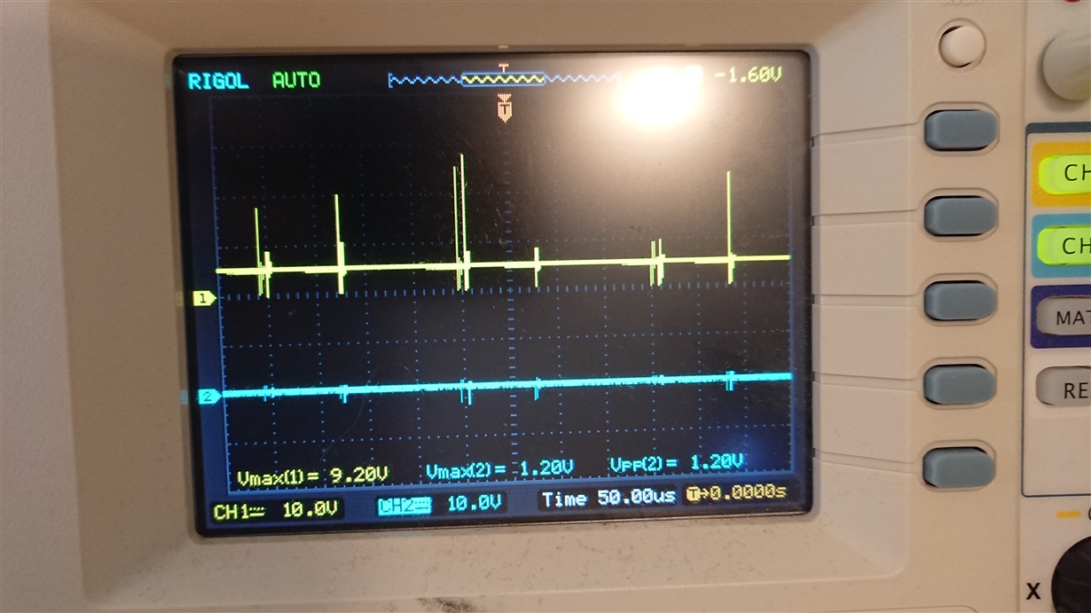
I identified the problem as being with 'R14' - I had taken the documentation too literally and set the resistor to 0, which was passing no voltage to the EN_UVLO and therefore the fuse was shutdown permanently. After replacing the resistor with a 430k, to produce a undervoltage limit of about 4.6V (by my calculations) the eFuse is now passing current, but instead my scope trace comes out like this (yellow is input power, blue is output):

In the interest of time, I need to eliminate any still-standing issues with my original design, can anybody see any other mistakes I've made that could result in unusual behavior such as this?

If not, could this behavior be indicative of a fault further down the chain from my included schematic, such as a poorly fabricated section of the PCB/short circuit?

To me, my inexperienced impression is that the eFuse is repeatedly going into shutdown for some reason due to the way the power line signal behaves, but that's not backed by anything solid.

Thanks in advance,

Louis

  • Hi Louis,

    What is the max. load current on 3V3?
    Looks like the device is fast-tripping. First try using DV_DT cap between 470pF to 1nF at pin '1' of TPS25923, if it did not solve, then set the turn-ON voltage of TPS6209733 at 4.4V using resistor divider at Enable pin. Setting turn-ON voltage of TPS6209733 at higher voltage help avoid loading the eFuse during start-up.
    Also make sure that the input power supply to eFuse is not getting current limited.

    Best Regards,
    Rakesh
  • Hi Rakesh,

    I've made the alteration of adding a 470pF to pin 1 and now the eFuse is passing no current at all.

    The max load on the 3V3 line is roughly 200mA, purely used for logic level conversion of certain IO.

    The voltage threshold is actually set higher than 4.4V, as per my original post, to 4.6V.

    Do you need any additional information or schematics?

    Many thanks,

    Louis

  • Hi Louis,

    Pls send me the waveforms of
    Vin, Vout, Iin, EN just after power ON
    Vin, Vout, Iin, BFET just after power ON
    Both zoom-in and zoom out versions.

    Have you checked your system by disabling U20?

    Best Regards,
    Rakesh
  • To solve this I doubled back and stripped my PCB design clean. I then re-fabricated the three power stages individually testing after each completion until I reached the 5VA output, which is having an unrelated issue. I can only surmise that the eFuse was interacting with a downstream component failure/short, and causing a repeated brownout.