This thread has been locked.

If you have a related question, please click the "Ask a related question" button in the top right corner. The newly created question will be automatically linked to this question.

TPS3828: WDI & Reset signal behaviour

Part Number: TPS3828

Hi Team,

In my company we use the TPS3828-33DBVT watchdog timer in one of our products and i would like to ask couple of questions for validation purposes.

1) Does the TPS3828-33(open drain) requires an external pull up resistor on the Active low RESET signal?  I ask because i have probed the reset signal using oscilloscope and i have observed that the signal is pulled HIGH. Is it pulled high internally? 

2)In our design we did not include a pull up resistor on the reset signal. Will it be safer to use a push pull version? 

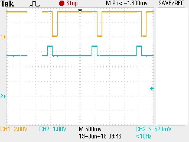
2) I have noticed that when the micro controller is not programmed, the WDI signal (CH2 on the image below) is toggling from 3.3V to 2.9V and the RESET signal (CH1) triggers from 3.3V to 0V. The WDI signal is pulled high to 3.3V using a 10kOhm resistor. Is a 10kOhm pull up resistor the right value?
Why the WDI signals toggles from 3.3V to 2.9V?


Regarding to the schematics, we do not use a pull up resistor on RESET signal as i have already said and also we do not use the(active low MR) pin, it is floating. 
 
Thank you.

Best Regards,
Kostas Papouis

  • Kostas Papouis,

    1. For Open-drain devices, a pull-up resistor is required due to the configuration of the internal output MOSFET. A pull-up resistor should be chosen so that the pull-up voltage divided by the pull-up resistance should keep the reset current (I_RESET) within the absolute max of 5mA.

    2. If you are not using a pull-up resistor, then you should choose a push-push device.

    3. If the microcontroller is in the high-impedance state, the device will internally generate a WDI pulse which is what might be happening. Be device needs to receive a positive or negative edge within the watchdog timeout otherwise the /RESET will trigger. If not using the watchdog, leave WDI floating. If WDI is connected to a microcontroller, then be sure the microcontroller is sending the correct signal. You should not have a pull-up resistor on WDI if using the watchdog.

    Please let me know if you have any more questions. Thanks!

    -Michael 

  • Hi Michael,

    Thank you for your clear answers.

    I believe the problem we had was the fact that we were pulling the WDI high to 3.3V using a 10k Ohm resistor.

    After removing the pull-up resistor i was able to capture the following WDI signal (CH2) on the oscilloscope which i believe is the internal oscillated signal generated by the watchdog timer. Is that correct?
    You can see also the reset signal (CH1) which is now not being trigger low as it was when the WDI signal was pulled high through a 10kOhm resistor.  


    Best Regards,
    Kostas Papouis 

  • Kostas Papouis,

    That looks correct. Please let me know if you have any other questions or need any additional support. Thanks!

    -Michael