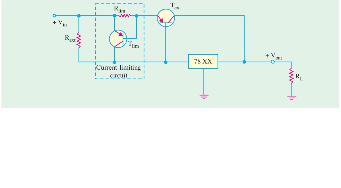
Can anyone offer some input as to whether the below schematic and explanation regarding using the internal protection provided by the LM78XX LM317 is correct for current limiting. Should I not have to worry how much current from Tlim passes through the 78XX in order to short/ remove the Base Bias of Text, or is it going to shut down when the temp/current limit is reached without frying? The datasheets do not appear to provide a similar usage! Under simulation circumstances it appears very difficult to not exceed the 1.5A Max of the Chip as well as set the Max current for the Text!
Please refer to the text below the image.
Regulated Power Supply 2181
Fig. 56.25
If the current through Text exceeds a certain maximum value, (Iext(max)) because of a shorted out- put or a faulty load, the voltage across Rlim reaches 0.7 V and turns Tlim on. As a result, Tlim now conducts current away from Text and through the regulator. This forces a thermal overload to occur and shut down the regulator. Remember, the IC voltage regulator circuitry is internally protected from thermal overload as part of its design. This way the external pass transistor is protected from excessive current.


