Because of the Thanksgiving holiday in the U.S., TI E2E™ design support forum responses may be delayed from November 25 through December 2. Thank you for your patience.

This thread has been locked.

If you have a related question, please click the "Ask a related question" button in the top right corner. The newly created question will be automatically linked to this question.

LM5117: SW ringing in DCM

Part Number: LM5117

Hi experts!

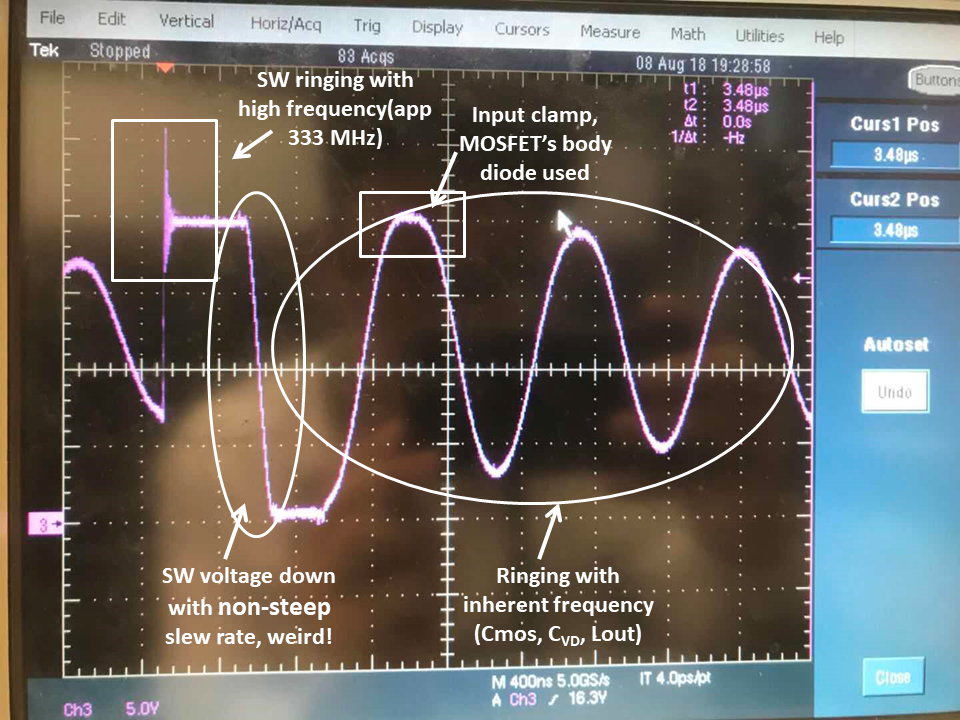
This is Wenhao who is testing LM5117 EVM. A normal but also weird SW voltage waveform emerges when I  connect VOUT to non-load. 

The circled areas refer to what I feel confused. While I can nearly understand why there would be a ringing after inductor current turns to zero and how this ringing will be clamped by input voltage but I cannot understand and how to analyze that SW ringing even after I have full read the sw ringing paper drawed by Robert Taylor. Therefore, could you please help me analyze the circuit model (parasitic parameters included) when High side MOSFET turns on? And if it is possible, could you also tell me the differences of modelling of those two different SW ringing? Thank you very much for you time answering me questions! It will be extremely kind!

  • Wenhao,

    Box 1: The first ringing (HS FET turns on) is caused by the parasitic inductance in the loop in the layout (loop = SW to L to COUT back to GND (and bond wires which is why we like flip-chip hotrod)) resonating with the parasitic capacitance of the inductor (and layout).

    Circle 2: The second lower-freq ringing is caused by the parasitic capacitance of the FETs resonating with the inductor L. The LS FET turns off when IL reaches zero but it's not perfect so there's still a little bit of current in L. The amplitude of this current (and the damping/frequency of the resonance) will control the amplitude.

    Box 2: If the lower-freq ringing amplitude is too high, it will be clamped by the body diode of the HS FET as you marked with the second white box.

    Circle 1: The slow ramp down when HS turns off and LS turns on is because the inductor doesn't have much current to quickly pull this down. This node has some capacitance so when the load is small, the inductor can't discharge those caps very quickly so there is some pseudo-slew-rate-control.

    Let me know if anything is unclear.
    -Sam
  • Hi Samuel,

    Thank you for you time! Your help makes me have a good start! I will figure out the modelling myself.

    Wenhao