This thread has been locked.

If you have a related question, please click the "Ask a related question" button in the top right corner. The newly created question will be automatically linked to this question.

UCC28780: More questions about Mathcad worksheets

Part Number: UCC28780


I was suggested to use following equation to calculate time related Coss of Main and Clamp MOSFETs.

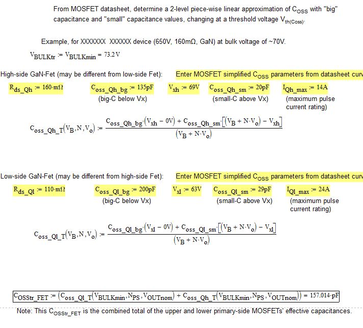
How to select Coss_bg, Coss-small and threshold Vxh value from the Coss curve?

Please help me with example. If possible please give me values for the following curve.

  • Hello Nisarg,

    Thank you for your interest in the UCC28780 ACF controller.

    The estimation of values for Coss_big, Coss_small, and Vx are based on effectively linearizing the MOSFET Coss curve into 2 levels. The example curve that you present is a particular challenge because there is no clear, narrow Vx range between high capacitance and low capacitance.

    In this Coss curve example, Coss starts at ~12000pF and drops to ~8000pF between 0.1V and 1V. Then it drops to ~3200pF by 10V. BY 20V, Coss has dropped to ~600pF and decreases more slowly every 10-V delta from that point on to about 60pF above 100V. A rigorous estimation of time-related Coss would involve integrating the total charge as Coss changes for small increments of Vds. The big/small approach is intended to simplify this estimation, but works better when the Coss curve has a sharper deviation over a narrow voltage range, like some currently popular MOSFETs show.

    In this particular case, I would guess that the Coss_bg value to be ~6000pF and extend this value out to ~15V, then drop Coss_sm to be ~120pF. Although Coss shows to be <70pF above 100Vds, I bias the Coss_sm estimation up to 120pF to accommodate the higher Coss charge variation between 15V and 100V. I admit there is a fair degree of guess work involved; however, the 2-orders-of-magnitude difference in “big” capacitance over ~15V tends to diminish even a large error in “small” capacitance over 500V. Thus, Coss_bg = 6000pF, Coss_sm = 120pF, Vx = 15V.

    Ultimately, the error in estimating Co(tr) (which is used to calculate the magnetizing inductance needed to satisfy the collective timing segments of on-time, demag-time, and resonance-time for a desired minimum switching frequency) results mainly in an error in the resonance-time segment of the switching period. This segment typically constitutes around 5~15% of the total maximum period, so the error will not affect the actual minimum frequency by much, maybe a little lower, maybe a little higher than calculated.

    I hope this helps to clarify this concept and method.

    Regards,
    Ulrich