This thread has been locked.

If you have a related question, please click the "Ask a related question" button in the top right corner. The newly created question will be automatically linked to this question.

TPS548D22EVM-784: TPS548D22 OVP

Part Number: TPS548D22EVM-784
Other Parts Discussed in Thread: TPS548D22

Hi Team,

I am curious about a problem: the TPS548D22 OVP circuit only reaches a minimum on-time after reaching the reverse maximum current limit, which makes the TPS548D22 enter the UVP state, which is equivalent to extending the OVP time, which is not conducive to the next startup of the TPS548D22. . What is the purpose of this design?

I'm looking forward to your reply!

  • Olin,
    We'll get someone to look at this after the holiday.
  • Hi Olin,
    We design the OVP circuit this way to protect the IC from damage due to high negative current, particularly if the inductor become saturated. The 1ms delay at UVP threshold voltage is to alleviate the VOUT negative ringing which can potentially damage the IC as well.
    Thank you.
    Amnat
  • Hi Amnat,

    Thank you for your reply. However, I have two other questions. The first question: If the negative current has not reached the maximum limit, what is the next step of the TPS548D22? The second problem is that when the negative current limit is reached, the action of the TPS548D22 is "the low-side FET is turned off and the high-side FET is turned on again for a minimum on-time".  Whether the low-side FET is always off until UVP.? If so, will the negative current charge the input capacitor in reverse (if the voltage source does not accept sinking current).

    I'm looking forward to your next reply!

    Olin

  • Hi Olin,

    First question: Once the OV comparator is tripped, the low-side FET will stay on until the negative current is reached.

    Second question: If the low-side FET is turned off and the high-side FET is turned on again for the minimum on-time. This action will continue until the output voltage gets pull down below the UVP threshold. During the high-side on for a minimum on-time, the inductor current is flowing in the positive direction but still in the negative region. Yes, this will charge the input capacitor for a brief moment if the voltage source does not accept sinking current. However, the input capacitors voltage rating should be selected with this in mind.

    Amnat
  • Hi Amnat,

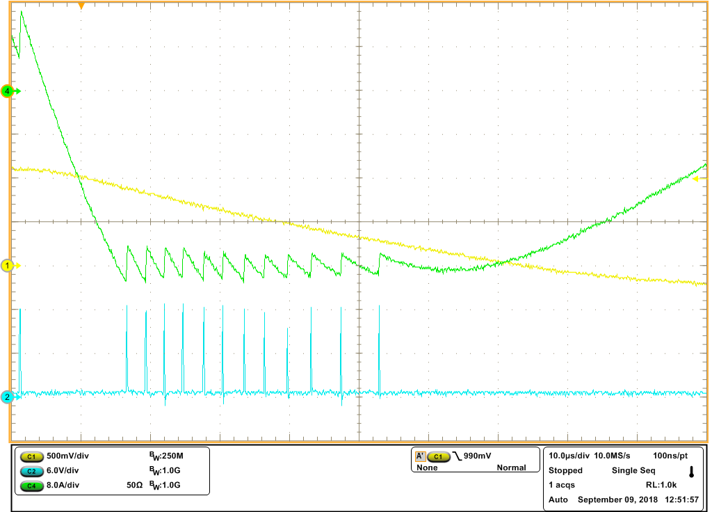
    The figure shows the OVP of the tested TPS548D22EVM. The actual measured delay time at UVP threshold voltage is not about 1ms, but about 35us. Can you explain this situation?

    Thank you.

  • Hi Olin,

    I will get back to you on this and will reopen the thread. Thanks for your patience.

    Amnat
  • Hi Amnat,

    I am also working on 548D22 because I am going to test newly-generation one.

    Related to issues in 548D22's OVP actions, I think it could be better if you can explain those actions in more details. Besides, I also have some questions related to this if you do not mind.

    1. From Olin's last testing waveforms, I can see Negative current limiting triggers when negative current is app 35.2A, where the point is not right coz the set negative current limiting point shall be over 40A. What is the cause?

    2. The second one is high-side MOSFET's off-time after UVP threshold is triggered is increasing, leading to negative current increasing again, does it means that high-side MOSFET would not be activated after negative current reaches negative threshold?

    Thank you for answering me those questions.

    Wenhao


  • Hi Olin and Wenhao,
    Would you please include the FB node when doing this test again? Also, are you getting ~40A when performing the regular OCP? Would you please check?
    Thanks,
    Amnat
  • Hi Olin and Wenhao,

    The attached report should explain all your questions.

    Thank you.

    Amnat

    TPS548D22 OVP Operation.pptx

  • Hi Amnat,

    I can explain this.

    1. If FB node was included, some noise will be injected by probe loop which cause control unstable.

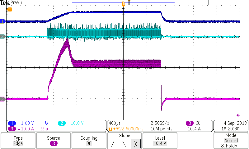
    2. Normal operation, the OCP threshold is 40A, which is shown as latch-off waveform below.

    If there is anything making you confused or want me to check again. Please ask me whenever you want. Thank you for you patience.

    Wenhao

  • Hi Amnat,

    Thank you very much for you patience answering my question. Your report completely solved my questions. It is so lucky that we have a patient and professional expert like you! Thank you again!

    Wenhao
  • Hi Wenhao,

    From the look at the valley current of the OCP threshold, it's pretty similar to the negative OCP valley value (~35A).  This is a normal operation.  I have nothing more to ask.  I'm glad the report is useful for you.

    Thank you.

    Amnat

  • Hi Wenhao,

    From the look at the valley current of the OCP threshold, it's pretty similar to the negative OCP valley value (~35A). This is a normal operation. I have nothing more to ask. I'm glad the report is useful for you.

    Thank you.

    Amnat
  • Hi Amnat,

    Thank you very much for you patience answering my question. Your report explains the OVP process in such a way that it perfectly answers my question. Thank you!