This thread has been locked.

If you have a related question, please click the "Ask a related question" button in the top right corner. The newly created question will be automatically linked to this question.

LMG5200: What is the requirement for PWM input with the LMG5200 to build a Class D amplifier?

Part Number: LMG5200
Other Parts Discussed in Thread: TPA3116D2,

Hello, TI engineer!

I have some questions about the LMG5200 and I hope you can help me.

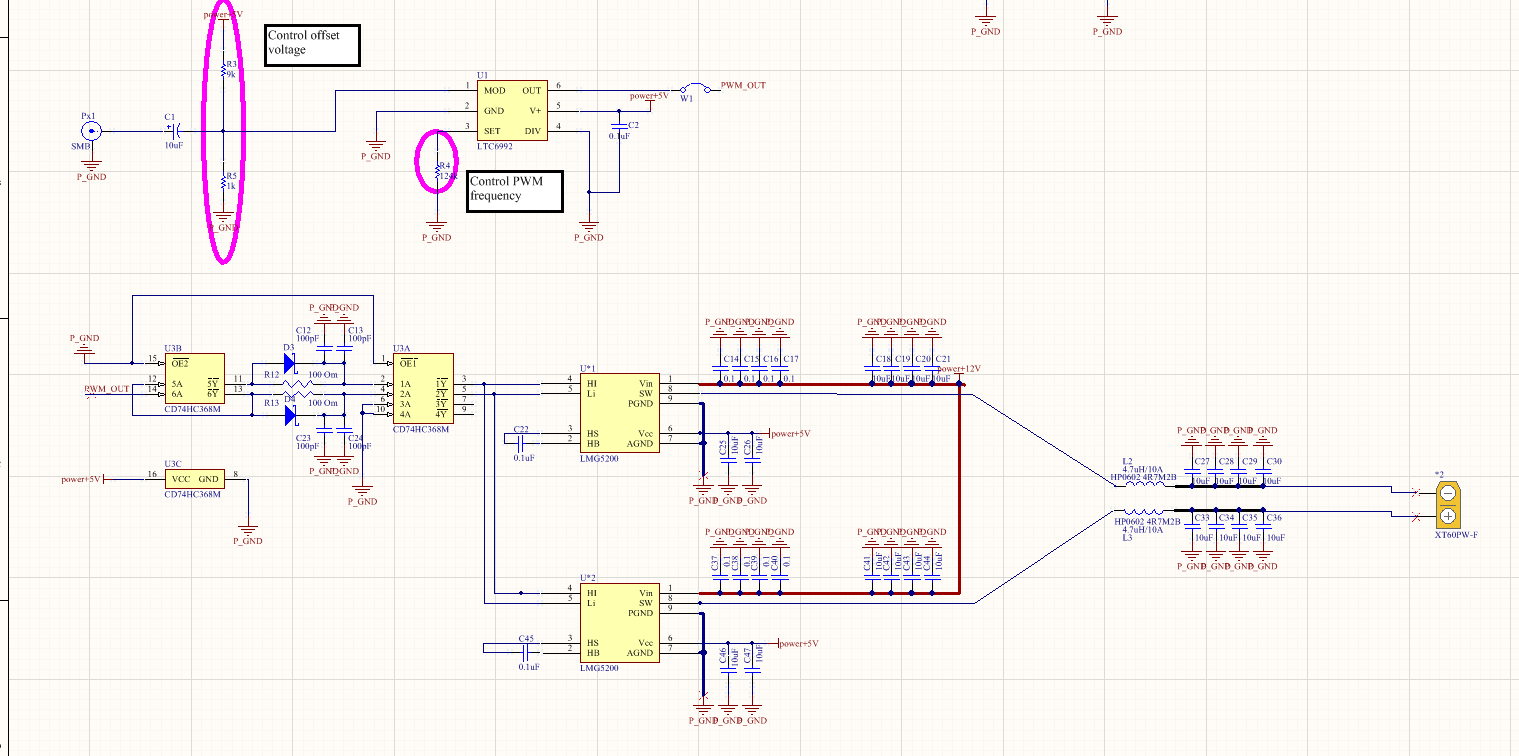
Recently, I am studying the use of LMG5200 to build Class D amplifiers. However, I have some doubts about the PWM input requirements. I have found a PWM modulator that can satisfy the PWM modulation function, but the output power of the amplifier cannot be improved. When the output power is large. The output waveform will have problems. Now it can only output a few watts of power, which can't meet my requirements.
I checked my circuit repeatedly, I feel that it is a problem with the PWM modulation chip, so I would like to ask what is the requirement for the PWM input?

Please reply to me after seeing this post, thank you very much!

  • Hello,

    Thank you very your question and welcome to TI E2E. Please refer to our LMG5200 datasheet for details about the input. Typically, you have to meet our input logic voltage level requirement to allow the FET to switch. Low logic has to be below 1.48 V and high logic needs to be above 2.22 V. At the same time, you have to supply 5 V to LMG5200. Please check your schematic to see if your controller output PWM signal can meet this requirement.

    Thanks and regards,
    Lixing
  • Thank you for your reply. I can satisfy the requirements you said. This is the D-class power amplifier schematic I designed with reference to the LMG5200EVM-02. If I replace the LTC6992 with the TPA3116D2, this amplifier can better implement the power amplification function, but these two chips are used as PWM input functions. The output waveform can perform PWM modulation well, but the output signals of the Class D amplifier are quite different.

  • Hello,

    Have you compared the two outputs from two PWM modulators? Are they exactly the same?

    Thanks,

    Lixing

  • Thank you for your reply.

    I compared the PWM waves output by the two chips, but I only compared the duty cycle of the PWM wave. The duty cycle is only a little different. I think it should not be because of this. For the spectrum of PWM I don't know how to distinguish the difference between the two.

    I compared the waveforms of each part of the two chip components, except that the waveform of the amplifier output is different. I really can't think of any problems with my PWM modulator that would cause my Class D amplifier power to not improve. I hope you can give me some ideas.

    thank you very much!

  • Hello,

    I see that after the PWM modulator, you have a buffer. Have you compared the two signals after the buffer, which are the signal input to the LMG5200? When you see different output at LMG5200, I still doubt if the two signals from the controller are different. Please compare them in detail, and also talk to the engineers who are in charge of the modulators. 

    There is an easy way to see if the LMG5200 is working right or not. Please probe both the input and output of LMG5200, and have them in the same oscilloscope screen. See if the output is following the input well. If yes, it should not be the issue of LMG5200.

    Thanks and regards,

    Lixing

  • Thank you for your reply! I will continue to check my circuit, if you find any problems, I hope you can help me.

  • I think I should find the problem, my PWM modulator may not have enough triangular wave amplitude, resulting in distortion of the final signal.Thank you for your patience.
  • Thank you very much. I’m glad you found the problem!