Because of the holidays, TI E2E™ design support forum responses will be delayed from Dec. 25 through Jan. 2. Thank you for your patience.

This thread has been locked.

If you have a related question, please click the "Ask a related question" button in the top right corner. The newly created question will be automatically linked to this question.

LMG5200: Using the LMG5200 chip as a Class D amplifier, what are the requirements for PWM input?

Part Number: LMG5200
Other Parts Discussed in Thread: TPA3116D2,

hello!

Recently, I used the LMG5200 chip to build a Class D amplifier, but when I chose a different PWM input chip, I had different effects.

Solution 1: Use TPA3116D2 chip as PWM modulator

This kind of scheme can better realize the function of the class D power amplifier, which is the waveform of the output of the class D power amplifier (the load is 4 ohms).

However, we consider that the TPA3116D2 chip itself is a Class D power amplifier. It is not very suitable to use this chip as a PWM modulator.So we changed a PWM chip.

solution 2: Use LTC6992 as PWM modulator

This chip can realize PWM modulation. In the experiment, we also confirmed that this chip can realize PWM modulation. However, if this chip is used as a PWM modulator, the output signal of the class D power amplifier will be deteriorated, and the power of the power amplifier cannot meet the requirements.

The following is the waveform diagram after we put the LTC6992 chip into the circuit.

Option One: We use 1KHZ sinusoidal signal to increase the signal amplitude test output signal

When inputting a 100mv signal, the resulting waveform is:

The above are the LTC6992 output waveform diagram, LMG5200 input waveform diagram, LMG5200 output waveform diagram, and filtered output waveform diagram.

After testing, in the case of 1Khz, the power of Class D amplifier can reach 20W (4 ohms).

Option Two: We use 4KHZ sinusoidal signal to increase the signal amplitude test output signal

 After testing, when the input signal exceeds 150MV, the output signal changes and the power requirement cannot be reached.When the input signal is less than 150MV, each part of the waveform is similar to the 1KHZ picture.When the input signal is 1KHZ, the output waveform is distorted after the amplitude of the input signal reaches 350Mv.

When the input signal exceeds 150MV, the waveform is as follows:
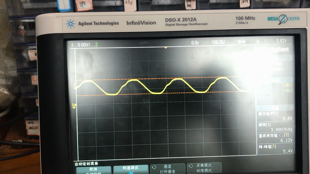
We can clearly see the waveform distortion, but when I choose the TPA3116D2 chip, the frequency does not appear when the frequency reaches 4KHZ. When the LTC6992 chip is selected, the power will decrease as the frequency increases, and only a small signal can be input to obtain a better output waveform.

Conclusion:

We don't know why there are such big differences between the two PWM modulators. What are the requirements for the PWM input of the LMG5200? How to solve this problem. If you see, trouble reply me. Thank you。

  • Hello,

    Thank you for your question. We have not seen this question before. LMG5200 is a power stage that can switch at DC voltage below 80 V, and need a PWM input above its threshold. When you are using LMG5200, please make sure that you have input signal logic above 2.22 V for high, and below 1.48 V for low logic. 

    Also since it is a GaN power stage, please make sure that you have dead time that is small enough. GaN has higher third quadrant voltage drop from source to drain during dead time, and this can lead to high loss. Please make sure it is small enough. 

    I recommend that you compare the PWM input signal in detail between different controllers. With the same modulation, your signal amplitude, and dead time may vary. If you have identical signals, you should have the same output performance.

    Thanks and regards,

    Lixing

  • Thank you for your reply.

    Thank you for your reply. But my problem should not be solved, I can meet the requirements you said, my PWM modulator output PWM is 0V and 5V. Regarding the design of the dead time, I refer to the dead time setting in the LMG5200EVM-02. The PWM modulation of both schemes can meet the requirements, but if the LTC6992 is used as a PWM modulator, the output signal spectrum of the power amplifier has a large influence on the low-order harmonics. When the TPA3116D2 is used as the PWM modulator, the output signal spectrum has low-order harmonic effects. Very small, so I want to ask what is the requirement for the PWM modulator.

    I hope you can help me solve this problem.

  • Hello,

    Similar to my answers in the other thread you had, LMG5200 is just a power stage, which is like an amplification stage of the PWM signal input you had to the IC. I suggest you compare the output of the two PWM modulators, and see if the signals are the exactly the same. The output of LMG5200 should be a reflection of your PWM signals. Any harmonics that you see at the power stage outputs should be also existing in the PWM signals.

    Thanks and regards,
    Lixing