This thread has been locked.

If you have a related question, please click the "Ask a related question" button in the top right corner. The newly created question will be automatically linked to this question.

RTOS/BQ34Z100-G1: I2C Writing and Reading to the bq34z100

Part Number: BQ34Z100-G1
Other Parts Discussed in Thread: CC1310, , BQSTUDIO, EV2400, BQ34Z100EVM, GPCCHEM, GPCRB

Tool/software: TI-RTOS

Hello,

I'm using CC1310 with BQ34Z100-G1 for Battery monitoring application. I need help in programming side to read data such as Voltage, SOC, current, etc.

I'm attaching my schematic. Application is for 48V(12Vx4) Li-Ion battery.

Can I get reference  code for the same?

Fuel_guage_PDF.pdf

Thank You

Viraj

  • Hi Viraj,

    For configuring the bq34z100-g1 device, the EV2400 + bqStudio GUI should be used. When the firmware image is ready for the device, the DFFS format may be used to easily write the initial configuration of the device for production. More information on DFFS format and gauge communication with C examples may be found here:

    www.ti.com/.../slua801.pdf

    For communicating with the CC1310, there is not a specific example with the bq34z100-g1. However, there are some ROM gauge examples that show how to communicate with gauges via I2C. The bq34z100-g1 is flash based, so the configuration will not need to be send to the gauge (as with the ROM gauges).

    Some code snippets and examples may be found here:

    www.ti.com/.../boostxl-batpakmkii


    Sincerely,
    Bryan Kahler
  • Hi Bryan,

    Thanks for the reply.

    currently i'm not having EV2400, so how can i configure bq34z100-g1 device with i2c from cc1310?

    regards,

    Viraj Cholera

  • Hi Viraj,

    Unfortunately you must use EV2400 and bqStudio during your development of a golden file to use with bq34z100-G1.
    The development process looks roughly like this:
    - Configure jumpers and basic dataflash parameters on your bq34z100EVM to enable working with your desired pack voltage.
    - Collect IVT logs while discharging per the instructions for GPCCHEM, submit logs and get your best matching chemID by email.
    - Use bqStudio and EV2400 to program that chemID into the bq34z100-G1.
    - Perform a learning cycle to optimize Qmax and Ra of the gauge.
    - Perform any other testing and modify other settings of the gauge until desired performance and behavior is achieved.
    - Export a golden .df.fs file which you can use to flash gauges in production via your MCU.

    If you see poor low temperature performance then you might also need to use the GPCRB tool to optimize the battery profile.
  • Hello dMax,
    thanks for the instructions,
    - How can i check I2C write operation is success or not? Is there any register that i can check my I2C write operation?
    - I have to change configurations for: PbA 48V(4x12V). Procedure to change configurations, I'm using Arduino.

    Regards,
    Viraj
  • Hi Viraj,

    After writing the value to the gauge, please read the value to see if the value set.

    Please use the EV2400 + bqStudio to configure the device initially following the steps outlined by dMax above. The DFFS is what you will use to program the gauges in production via your Arduino.

    Sincerely,
    Bryan Kahler
  • Hello Bryan,
    We have BQ34z100-G1 mounted on our PCB as shown in schematic shared in previous message.
    If we have EV2400, then shall we able to configure our BQ34z100-G1 using it without having bq34z100EVM?

    Thanks.
  • Hi Viraj,

    Yes, the EV2400 may be connected temporarily to a custom PCB in order to program and/or log the device. Please ensure that the EV2400 and the BQ34z100-G1 are the only two devices communicating on the I2C bus during programming and logging with bqStudio.

    Sincerely,
    Bryan Kahler
  • Hi,

    We have completed the learning cycles, but still state of charge is 0% and error is 100%.

    Also we are unable to change design capacity.

    Please let's know if we are doing any thing wrong.

    Thanks & Regards,

    Viraj Cholera

  • Hi Viraj,

    One possible reason that you are unable to change design capacity is because the device is prevented from performing writes to dataflash.  If you are unable to make *ANY* writes to data flash, ensure that the per cell voltage to the device is > 2.8 V, FLASH UPDATE OK VOLT is 2800 mV or lower, voltage divider is set properly, series is set properly, voltsel = 1 and the device has undergone voltage calibration.

    Sincerely,
    Bryan Kahler


    Find out more about the BQ34Z100-G1 including technical documents and tools/software/firmware and frequently asked questions.  Refer to the quickstart guide to get up and started. Also, learn how to find your chemID and perform voltage and current calibration.


  • Hello Bryan,

    Thanks for the reply.

    I had set voltsel bit to 1, Voltage calibration is done properly, Voltage and current reading shows correct, CHEM ID is updated, but when i try to change device capacity, it is not changing, Device capacity shows 1000 mAh. 

    Thanks

    Viraj Cholera

  • Hi Viraj,

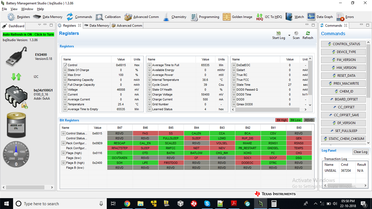
    Please ensure the device is in an unsealed full access state prior to writing the design capacity to data memory. First unseal the device (state as shown in the screenshot), then perform the unseal full access command.

    Sincerely,
    Bryan Kahler