This thread has been locked.

If you have a related question, please click the "Ask a related question" button in the top right corner. The newly created question will be automatically linked to this question.

UCC27714: UCC27714

Part Number: UCC27714

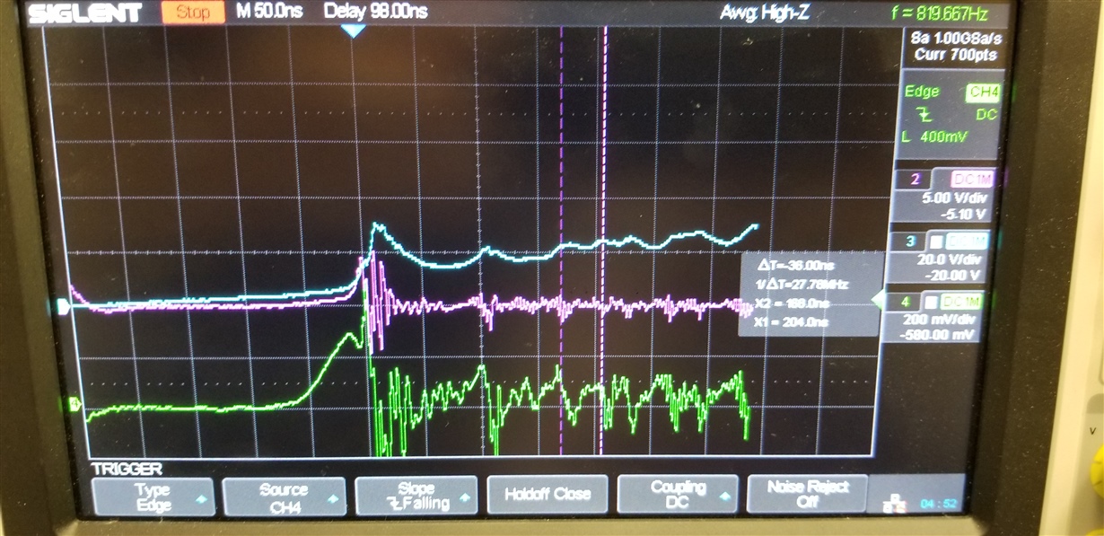
Green trace = I drain. Blue trace = V drain.

  • After turning off the bottom MOSFET while there is reverse current in the bottom MOSFET (with VS about 0.8V below ground) the HO output cannot go high. When the bottom switch is turned off, oscillations occur due to Crss of the bottom MOSFET being higher off but this should not affect the top switch. The scope shows (VB - VS) of the top switch being pulled below the UVLO level during this time and then the top switch doesn't even turn on. What is causing the VB-VS capacitor to be drained during this time? How can this be prevented?

  • Hello Darrell,

    I am an applications engineer supporting this device, and I assume you are posting a question or concern on the UCC27714.

    Only the scope plot came thru on the post, with no description of the concern or details on the plot.

    If you have a question can you add additional information and we will respond with answers or suggestions.

    Regards,

    Richard Herring

  • Sorry, Darrell, for some reason our system let your first post go thru, but blocked the second one. I have fixed your permissions so you will be able to post without any issues going forward. Sorry!

    Richard, it now shows. Check the thread again.
  • Hello Darrell,

    If you could clarify which channel on the scope plots corresponds to the signals that will help.

    I hesitate to assume the signals, but it looks like channel 2 is the lowside FET Vds, showing going below ground due to body diode conduction.

    Channel 3 (blue) and channel 4 (green) is not so obvious which signals are shown.

    Can you provide the signal names, or more preferred would be a plot showing lowside FET Vds, HB-HS differential, LI and HI inputs.

    Also can you provide a diagram of the driver and support components including VDD capacitance, HB-HS capacitance, boot diode part number, boot diode series resistance.

    I hesitate to speculate on what may be causing the HB-HS bias to drop without some more information.

    Regards,

    Richard

  • Hi Darrell,

    It's been a while since we've heard from you, so we must assume you've resolved your issue.

    If possible, please post how it was resolved for others to learn from.

    If not, let us know, and we will work with you to resolve it.
  • Sorry for the delay of a week. (our IT at work blocks websites and I have to do this at home.) Channel 2 - Pink is the Gate of the bottom FET. Channel 3 - Blue is the gate of the top FET. Channel 4 - Green is the current-sense resistor - 17 mOhm at the source of the bottom FET. The FETs are 3-in parallel STB34N60. This is a pic of the gate drive circuitry; one of the R-D-R networks on each FET is shown in the pic. You can see the current (green) of the reverse recovery of the diode of the bottom FETs start to rise when the top FET gate reaches ~4V. When this Irr is finished you can see the voltage of the top FET start to rise (blue). Due to the gate-drain capacitance, Crss of the bottom FET being very high in the reverse-conduction state, you can see the bottom gate (pink) get pulled up by Crss until it's ~4V and it starts to turn on. From then on the whole circuit is unstable. What isn't shown is Vgs of the top FET: It gets pulled below the UVLO of the IC for some reason and then the top gate drive is off from then on.

    All I can conclude is that the 100MHz oscillations cause the top gate driver to discharge the HB-HS caps. I had to put 2 huge 10uF caps at HB to even get it to work to get the pic. 

    (I'll try to paste the gate drive circuit here. Last time the website went blank on me.)

  • that didn't work again . . . .trying to paste a pdf.
  • Hi Darrell,

    Sorry for the difficulty with our system!

    The .pdf was attached. Thank you. We'll be getting back to you shortly with suggestions.
  • Hello Darrell,
    Thank you for the clarification on the scope plot waveforms, and the circuit details. I looked at the diode datasheets, both the boot diode and gate drive turn off diode and they look like appropriate choices. If a slow recovery boot diode is used the HB cap can be discharged during the switch node voltage rising.
    The three MOSFET's in parallel with have fairly high gate charge at ~240nC. Look at the UCC27714 datasheet application section, but one quick way to confirm is for 240nC to result in a 1V drop on the HB cap the capacitance would be 240nF minimum.
    The low side FET miller charge induced spike and ringing during the high side turn on can be a result of the PCB trace inductance in the gate drive current loop, which is from the driver output to the MOSFET gate and the return from the MOSFET source back to the gate driver COM. Also the VDD cap needs to be placed close to the driver VDD and COM pins to minimize inductance.
    I am surprised that the HB capacitor is being discharged with such a large value in place, considering the time that the low side Vgs ringing occurs.
    It is possible even with a fast boot diode, that high frequency ringing on the HS node may result in repetitive reverse current, discharging the HB-HS capacitor. Try increasing the boot resistance, with the expectation that higher resistance will reduce the reverse current if this is the cause of the HB discharging.
    We typically recommend slowing down the turn on edge of the high side MOSFET to slow down the dV/dt and reducing ringing from the body diode reverse recovery. I see you have 100 Ohms turn on resistanc3e, but I would recommend you try increasing the turn on resistance to see if this helps.
    Can you send some plots showing the HB voltage as well, with the same time scale as before, and one at a time scale that shows the HO output turning off from HB declining.

    Regards,
    Richard Herring
  • Thanks for the advice Richard. Yes, slowing down the top FET turn-on may be a solution. Uncharted waters here because the MOSFET manufacturers don't give a Miller cap (Crss) spec at <0V but, that's the quadrant the FETs are put into when used as a sync-rect'r. The boards won't be available for waveforms for a week or so. I'll let you know the new results.

  • "We typically recommend slowing down the turn on edge of the high side MOSFET to slow down the dV/dt "  Once the top FET has enough current for the reverse recovery charge of the bottom FET's rectifier the top FET current will be the peak Irr (plus the circuit's inductor current). This Irr peak current will charge the Coss of the bottom FET rapidly, regardless of the value of the gate resistance. Additional gate resistance will cause a slightly lower di/dt at turn-on which in turn, causes a lower peak of Irr but this is at the cost of much higher switching loss.

    What I have found in both the model, and implemented in a previous circuit, is to add additional gate capacitance in the bottom FETs such that the miller charge will not force the gate voltage up to 4V, turning it on when it should be off. 

  • Hello Darrell,

    We haven't heard from you in a while. If you resolved the issue can you confirm and post on the thread so other users can benefit from your findings.

    We are going to go ahead and close the thread. If you have any more questions it will reopen if you post on this thread.

    Regards,

    Richard Herring