This thread has been locked.

If you have a related question, please click the "Ask a related question" button in the top right corner. The newly created question will be automatically linked to this question.

UCC28950: DB and DC near Ls overheating problem on 600W DC-DC 300V output 400V input

Part Number: UCC28950

Hello,

I resolved "Da" and "Db" problem choosing a TO-263  (D2PAK) fast switching diode, capable of carrying out the heat.

I have some remaining question to ask:

1) How do I set an optimum a compensation ramp with a primary current wave like this (the yellow trace which is descending instead of rising like in literature)? Has your colleague an idea about this?

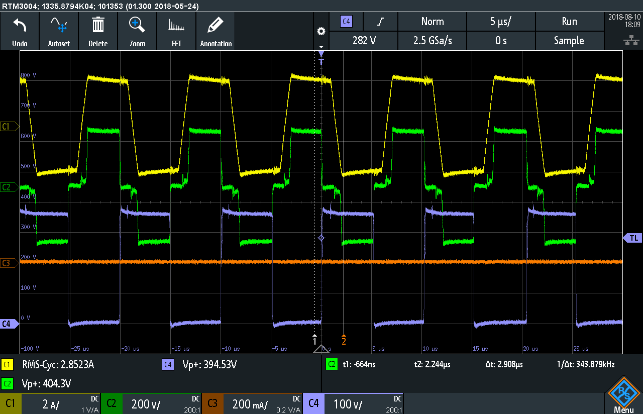
2)I ask the first question because testing with an electronic load i have some point in wich the duty cycle of the controller change rapidly (instability points?), anyway mantaining the regulation of the output voltage  like this:

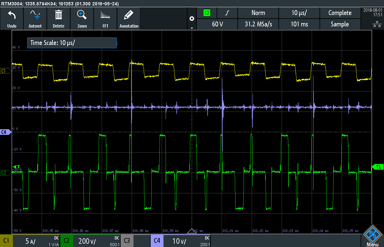
3)How do I ptimize EMI for burst mode? I have some devices capting noise during burst mode at light load. Is increasing the minimum pulse time a good point to start? Any other suggestion?

4) This is the "soft start" process: can you confirm that is all right? I have suspects regarding the first train of pulses (yellow primary current, violet controller 12V supply, green primary voltage)

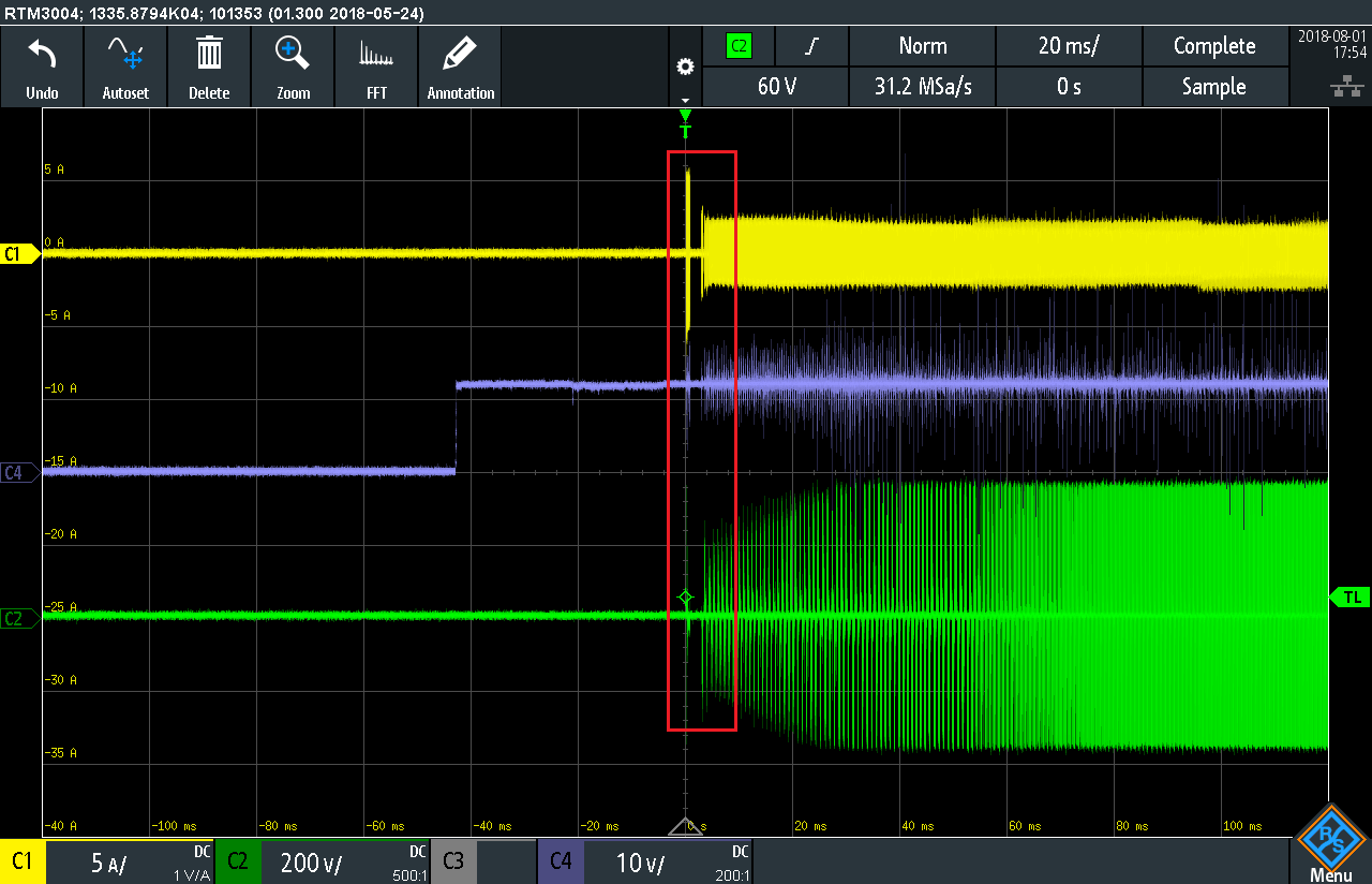
zooming the red rectangle the current is higher than current limit set, having some pulses at 100% duty cycle:

Thanks and regards

Francesco

  • Hello Francesco

    1/ We have once or twice seen a primary current ramp like this in a customer application. Unfortunately it was not in a TI lab and neither I nor any of my colleagues were able to understand what is causing it. I'd really appreciate if you can send me your schematic and I'll try to simulate this behaviour - you can email it to me at colingillmor@ti.com .

    2/ If you are using Peak Current Mode control then this looks like a sub-harmonic oscillation - I'm not sure how to deal with this given point 1 above.

    3/ EMI in burst mode is unlikely to be worse than EMI in normal running mode so I would concentrate on the EMI during normal operation - this usually means operation at full load.

    4/ If VCC comes up before the voltage to the power train then it may be that the soft start interval is over before the voltage at the power train rises. I'd check this by looking at the SS/EN  pin during this time. Soft start should look something like the image below (fromt he EVM). Yel: OUTA, Red: OUTB, Blu: Voltage across the transformer, Grn: Vout. This was taken by applying VCC AFTER Vin. If you have to apply VCC first then you can use the ENable feature of the UCC28950 by pulling SS/EN low and then releasing it once Vin is established.

    Regards

    Colin

  • Hello Francesco

    Did you get a chance to look at this ? do you have an update for me ?

    Thanks
    Colin
  • Hello Colin and thanks for your feedback.

    Unfortunately I was out ot office during the last days, I will update you ASAP.

    I sent you schematics by email on 13th of july and also gerber files;

    The main differences in the power part are:
    - L2 (shim inductor) having a value of about 50uH;
    - the transformer ratio is elevator 360VIN 480VOUT without center tapping.


    I sent you by email my version of UCC28950 design excel which contains the values of the components, i think you can check something about the sub harmonics oscillation


    Thanks again and regards,

    Francesco