This thread has been locked.

If you have a related question, please click the "Ask a related question" button in the top right corner. The newly created question will be automatically linked to this question.

BQ24172: Can not charge the battery successfully

Part Number: BQ24172

I am using the BQ24172 to charge a 3-cell battery. I refer to the evaluation board circuit and built my PCB. The target is to charge the battery with 2A current. The input power is supplied from a 15V, 6A power adapter.

I have tested the battery by charging it with a standalone charging station at 2A current and verified it is okay.

When I switch on the power adapter, the LED (the STAT pin) light is ON without blinking. I guess it means there is no error on the circuit.

I connected an ammeter in between the battery and the PCB so that I can observer the charging current. I found that the charging current does go up to about 1.6A for a few seconds, then it drop back to 0. This iterate for a few times and then the current stopped.

The battery is originally at about 10.5V.

In the circuit I am connecting the TS equal to the evaluation board circuit by using a fixed resistor value.

I attached a table of the parameters I used on the circuit board, such as charging current, regulated voltage, and etc.

Can you give me any hints where can go wrong?

Thank you very muchCharger Prototype Calculation.xlsx

  • Hi,

    Could you please provide more information?

    1.When the charge current was abnormal, did the STAT pin blink at 0.5 Hz?
    2. How exactly do you connect the TS pin?

    Thanks,

    Ning.
  • 1. The STAT pin does not blink. The LED switches on in stable state (STAT pin at low level)

    2. The TS pin is equal to the evaluation board. A 5.23K pull up resistor, a 30.1K pull down resistor, and another 10K pull down resistor (to simulate a thermistor at 25C). A 100R and 0.1uF low pass filter at the TS pin. Btw I have also checked the voltage at the TS, it is within the cold and hot threshold.

  • To make it clearer, I attached my schematic about how the TS pin is connected. In my testing, I have shorted pin 2-3 of the jumper JP1.

  • Hi,

    1.The bq2417x calculation tool is downloadable at www.ti.com/.../toolssoftware. You may double-check design parameters.
    2. Is there gauge or protection IC in between the charger output and the battery? Or does the battery have built-in gauge/protector?

    Thanks,

    Ning.
    Please click "This Resolved my issue" button if this post answer your question.
  • One issue I found is that the LED switch on (no blinking) even I did not connect the battery. My expectation is it should detect the battery absent and the LED blink.

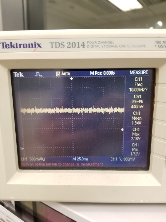
    Then I check the voltage waveform at FB pin, I got the following result. 

    Also some other information:

    (I am supplying about 15.1V to the charging board)

    - When I check the "TP1" (which is the BATDRV pin) at the evaluation board (bq24172EVM), it is 15V. However when I check that at my board, it is 11.8V.

    - When I check the "Vsys" on the evaluation board, it is about 15V. However when I check that at my board, it is 11.8V

    What could be the problem?

  • I have some new finding. After I changed the resistor value of R9 from 43Kohm to 36Kohm, it can charge the battery. However, the charging current does not go up to about 2A immediately, it rise from 0.5A slowly to about 1.5A.

    Also it still cannot detect the battery absent. In the other word, when I disconnected the battery , the LED still switch on.


    Another issue is I found the temperature of Q2 get super hot, over 100C, the PCB layout already have a copper pool for the Drain and Source pin for Q2. Q3 is not hot.

  • For question 2, yes there is a protection board in between the charger output and the battery. However I have tested the same battery with the evaluation board, it has no issue.

    Evaluation Board:

  • Gary,

    For battery detection, when the battery is not connected,

    1. How much total capacitance is connected to VBAT (charger output)? Please compare with Cmax below.

    2. Is there any load connected to VBAT?

    Thanks,

    Ning.
    Please click "This Resolved my issue" button if this post answer your question.

  • Today I make another board and test it with the battery......and it works! The battery absent detection is normal. The charging current reach 1.6x A (although I want 2A actually, I will investigate it later). The Mosfet does not get hot anymore, the hottest part now is the BQ24172 which is about 50 degC.

    I do not why, I have re-soldered the component and checked the original board already. Anyway at least it works now.
    (I have another question but I will open another post.)

    Thank you very much for your help.
  • Hi,

    It's great that the battery detection is normal now.

    For the device thermal performance, it is critical to solder the exposed thermal pad on the backside of the IC package to the PCB ground and ensure that there are sufficient thermal vias directly under the IC, connecting to the ground plane on the other layers. Please refer to the bq24172 EVM for sample layout.

    Thanks,

    Ning.
    Please click "This Resolved my issue" button if this post answer your question.