This thread has been locked.

If you have a related question, please click the "Ask a related question" button in the top right corner. The newly created question will be automatically linked to this question.

LM2776: Sometimes the output is not correct (not the expected -5V but around -1.3V).

Part Number: LM2776

We have the same problem, we are using +3.3V as input to LM2776. When the circuit is loaded with 30mA(approx) between Vin and Vout, we are getting +0.6V (approx). If we load it with 25mA (approx), the circuit works well and LM2776 delivers -3.3V.

Is this expected?! Is there a way we can resolve this?! 

NOTE: I cannot reduce the load below 30mA

  • Hi Sathish,

    Can you post a waveform of Vin and Vout when it works and when it doesn't? Is EN connected to Vin?

    How are you applying the load current? Is this a resistor or electronic load or your real circuit?
  • Hi Sathish,

    Were you able to resolve this issue?
  • Hi Chris,

    We haven't fixed this issue yet. We did a few tests and here are the details.

    Schematic:

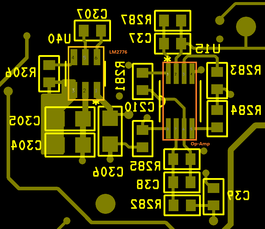
    Layout:

    BOM:

    U40 - LM2776DBVR

    C304, C305, C306 - GRM21BR71A225KA01K

    C307 - 0603X105K250CT

    R306 - RC0603FR-0710KL

    Op-Amp - LTC6244HV (Dual Op-Amp x 2)

    TEST: 

    We assembled LM2776 circuit onto a General Purpose Board for testing.

    Test Schematic:

    Here instead of Op-Amp, we used Resistors as loads for various current. And what we found is that when the load is below 30mA the circuit works as expected.

    But if the load is above 30mA, then the output becomes +0.6V (approx).

    Wave-forms (for the above test):

    Orange / CH1 is +3.3V (Probed on VIN) and Blue / CH2 is -3.3V (Probed on VOUT).

    1. When the load is below 30mA

    2. When the load is above 30mA

    Please let me know if you need any more details.

    Thanks

    Sathish

    Radio Studio, Chennai

  • Thanks for these details Sathish.

    Your output voltage is going positive somehow. This does not match any waveform in the D/S.

    Can you try replacing C307 with another one of the 2.2uF caps from Murata?

    You can also order the EVM to test a known working circuit.
  • Hi Sathish,

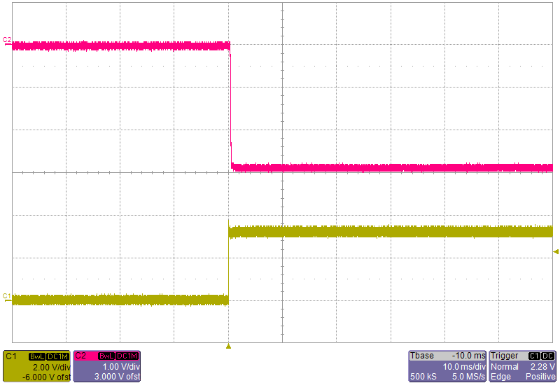
    I cannot see the positive voltage on our EVM:

    Yellow is Vin (hot plug) and red is Vout.

    Does this behavior show itself on all boards or just on 1?  Via the conversation, can you send me a more complete schematic showing the connections and components back to the input power?