This thread has been locked.

If you have a related question, please click the "Ask a related question" button in the top right corner. The newly created question will be automatically linked to this question.

UCC28740: Based a bias supply off of PMP20001 and it is not regulating the 5V

Part Number: UCC28740
Other Parts Discussed in Thread: PMP20001, UCC21520,

Was hoping someone could take a look at our schematic and see if there is anything obvious.  R68 has already been changed to 5 ohms (stacked 2 10 ohm resistors). And node between D2 and C86 should also be connected to VDD. Even with these changes I am not getting a good 20V on VDD and am wondering if that is the cause.  The other major difference is the fet in PMP20001 was listed as NRND so we substituted for a better one, does the Rds-on change the value of R70?

Thanks for any help.

  • Hello Matt,

    The VDD pin voltage is internally generated internally through the HV pin. The HV pin connects directly to the bulk capacitor to provide a startup current to the VDD capacitor. The internal HV startup is active until the voltage at VDD exceeds the turn-on UVLO threshold of 21 V at which time the HV startup turns off and the Vdd is generated through the Aux winding.

    If the 5Vout is not in regulation the Vdd is not regulated as well because it is sensed across the Aux winding.

    One thing to notice is that the PMP20001 is designed for 185VAC to 260VAC Input, if your input is lower than this range then the 13uF bulk cap is not sufficient to provide for the full load power, also the turns ratio of the transformer will have to be recalculated for the new primary voltage.

    Please plot P5V, FB and Vdd for a better understanding of the issue. At what input and output conditions do you observe the non-regulation, does it continue to happen when you increase the line voltage.

    You might already know it, but a good way to quickly review the component section for your specific design is the calculator tool attached below:

    Regards,

    Sonal

  • 750871630.pdfSonal,

    I have an auto transformer hooked up to get to voltage to approx. 220-230VAC. We are evaluating the attached transformer to get operation down to 85VAC but that will be the next problem. I am working on getting the scope plots now.

  • Hello Matt,

    For experimentation, you can also try to reduce the capacitance on the VDD pin by removing C62.

    Regards,

    Sonal

  • Hello Sonal,

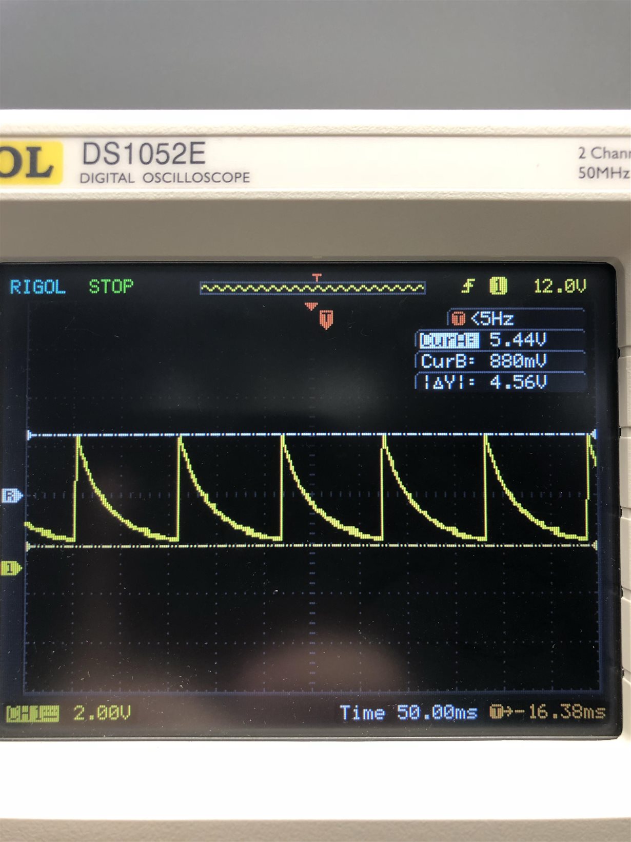
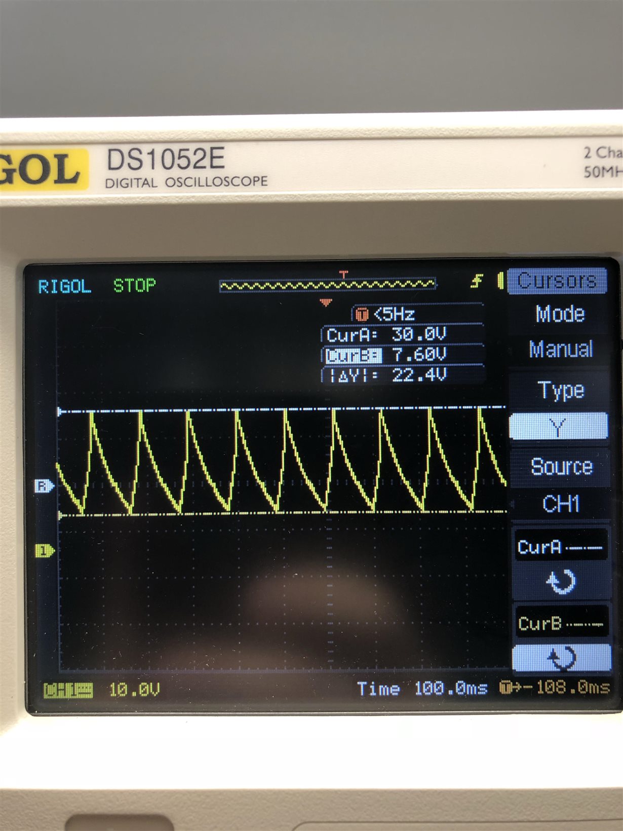
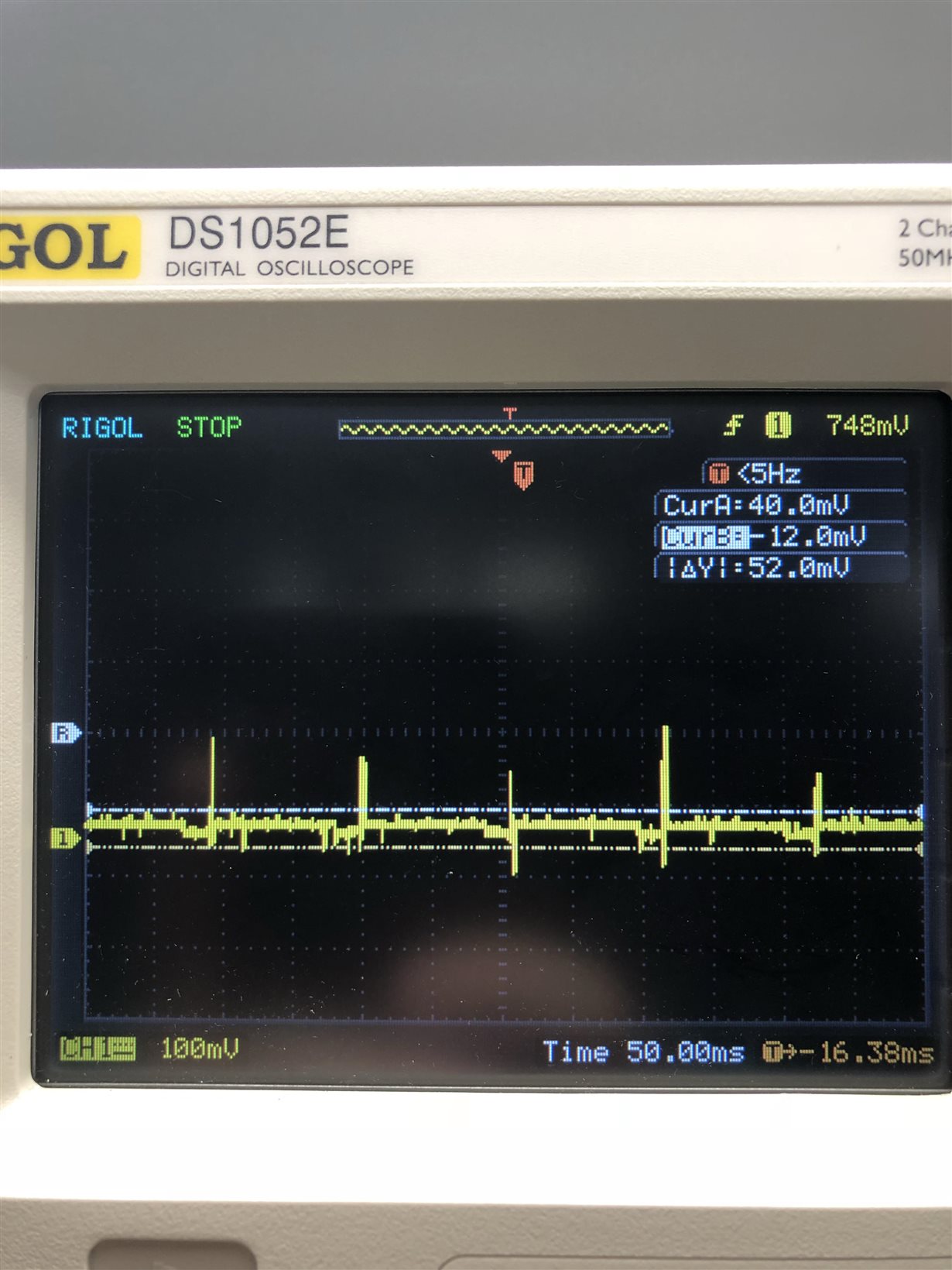
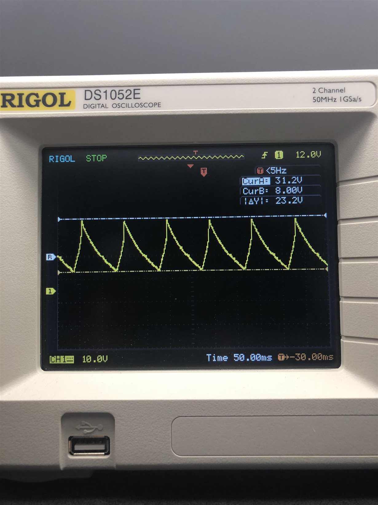
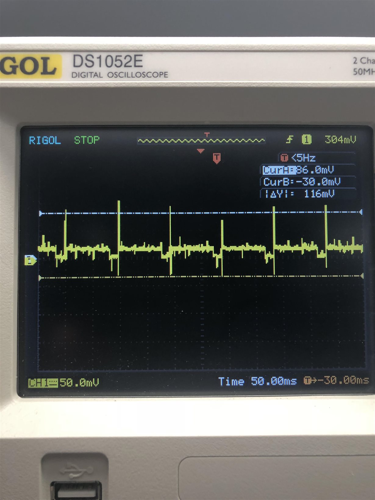
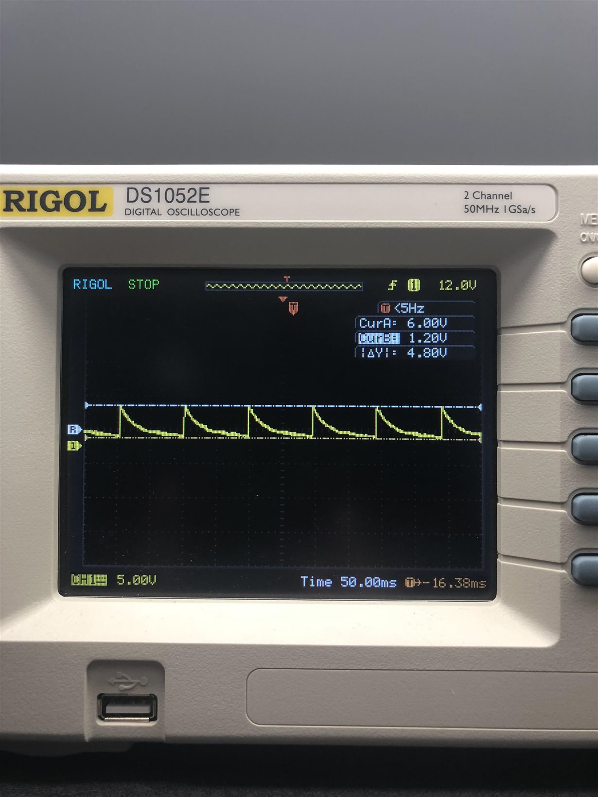
    attached are some captures of Vdd, Vfb and V5V. For these I have removed C62, also we have replaced C41 and C45 with 39uF electrolytics from the same series (nichicon UCS2G390MND)

    Attached are the 3 scope traces, It appears we are charging up but the FB signal is not regulating?  I am guessing we are tripping a safety and the chip resets?

    5V Output:

    Vdd

    Vfb

  • Hi Matt,

    As you can see that the Vdd voltage is following the 5V rail, which makes me think that the 12V rail might also be doing the same thing. This is because the compensation loop might not be stable. What is the load condition on both the rails?

    The difference between your and PMP20001 is the different Optocoupler, the gain (CTR range) on the FOD817A is very narrow as compared to the original pick, that is why the same compensation loop will not be valid. 

    If the FB is low this might mean that the optocoupler is projecting that the controller is in CV regulation and that is why the controller lowers the switching frequency, this causes the output caps to discharge as seen in the 5V output plot.

    It will be useful to see what the 12V rail looks like. Reducing the pre-load on the 5V rail might help as a quick option, I would recommend adding another 1k across the 5V rail.

    Regards,

    Sonal

  • the 12V is unloaded at startup, it only provides power to a 12V buzzer which is not active(500mA when active), the 5V is lightly loaded, its providing power to a PIC16, and a handfull of logic gates and op amps and 3 UCC21520.

    I will look at using the sluc487b spreadsheet to recalculate the compensation for the opto we have, also I will order some FOD817D which should have a comparable CTR range.

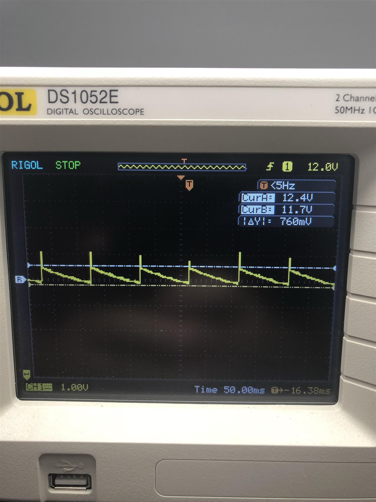
    The 12V has higher ripple but is much better than the 5V output

    For the preload on the 5V wouldnt we want to remove a 1K to reduce it, adding another would increase the load.

    Do you have an example of what the FB waveform should look like?

    Thanks!

  • Hi,

    Adding another 1k across the line will reduce the total pre-load resistor to 0.33k.
    IFB is a direct translation to what is the load on the output. the voltage on FB pin is low because you are in light load. This IFB sets the switching frequency and the operating point of the controller in CV mode. Please refer to Page 16 of UCC28740 datasheet.
    www.ti.com/.../ucc28740.pdf

    Regards,
    Sonal
  • Tried the extra 1K for preload, this is also with a FOD817D for the increased CTR ratio

    Signals are a little different but much the same.

    Vdd

    Vfb

    V_5V

  • Hi Matt,

    Does the 5V rail remain the same when the load is increased?
    If the power delivered on the 12V rail is higher than the 5V rail then you should not see this. One way to debug this is to go back to the original FETs and examine if you get this behavior there which is very likely to be the case.
    Modified FET will have a different Coss and Ciss which will cause a different turn-off delay from the original calculation but this will not make any change in the output regulation.
    I strongly believe this is a control loop stability issue and I will suggest you to use the PSD tool to recalculate the compensation elements. Meanwhile, I will get back to the team to check if they see the same issue on the original board, this might take several days.

    Regards,

    Sonal