This thread has been locked.

If you have a related question, please click the "Ask a related question" button in the top right corner. The newly created question will be automatically linked to this question.

TPS62135: Unexpected behavior at output.

Part Number: TPS62135

Hi!

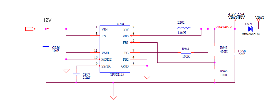
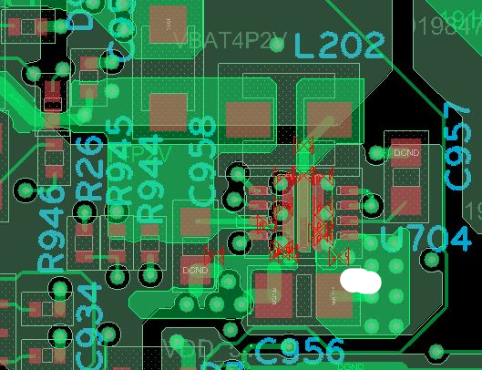
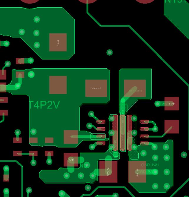
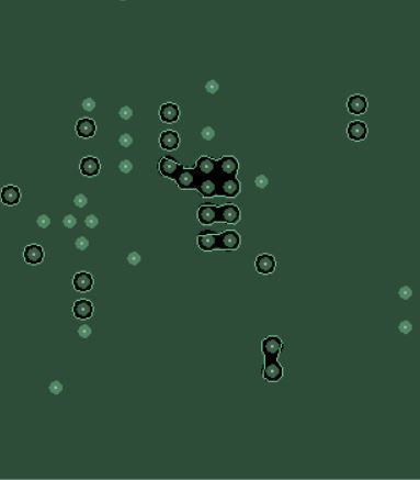
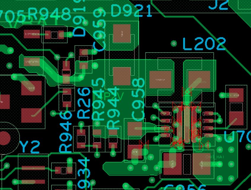
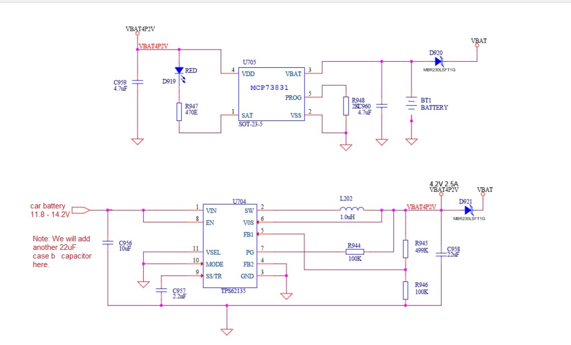
We recently integrated the step-down converter TPS62135 into our device. The device functioned as expected for three weeks and has now stopped working. We are currently not getting any output from the regulator. Can you please help us in identifying the problem and tell us if we have to follow any precautions while using the device. The schematics and PCB layout are attached below.

PS: We had one problem earlier as well (please refer to the thread "Unexpected behaviour at output.") but it was resolved as per the suggestion from Chris Glaser that the problem could be ESD. We have taken care of this.

  • Hi Nithish,

    ESD can also occur after assembly, so you should always be grounded when handing the PCB/circuits.

    Did just 1 part stop working or all of them? What does it do when it doesn't work anymore? Is it hot? Is it switching?

    Did you use the components listed in the Webench design or different part numbers?

    Can you post your layout images as 2 images: one of the top layer and one of the bottom layer?
  • Hi!

    Our device is packed in a plastic enclosure and two devices have failed. We have checked the output of the regulator with a multimeter. When it is not working it does not heat up and it does not give any output. We have used the same components as suggested by webench design, only change being we have used a 1/16 watt (62.5mW) 0402 resistor for R945, in contrast to webench designer's suggestion to use a 125mW resistor for the same. Attached below are the images of the different layers.

    Layer 1:

    Layer 2:

    Layer 3:

    Layer 4:


    Top view:

    Thanks.

  • Thanks for sharing.

    You'll need to open up a failed system and (while grounded) probe the IC's Vin, SW, SS/TR, and Vout pins to see what it is doing and what state it is in.

    What is your 12V input source? An AC adaptor? Is there any sort of circuitry between this and the IC? You may have hot plug overshoot as described here: e2e.ti.com/.../what-is-that-giant-tantalum-cap-on-the-input-of-the-evm

    Finally, the Cin C2012X5R1V106K085AC only gives ~1.5uF of effective capacitance at 12Vin. This is below the 3uF required by the IC. You might put two of those in parallel or use the TMK212BBJ106KG on the EVM instead.
  • Hi!

    We read 0V at SW, SS/TR pins and 12V-14V at the Vin pin. We are providing 11.8V-14.2V input from the car through a diode MBR230LSFT1GOSTR-ND ( Forward drop: ). At the input of the regulator we have a 10uF 50V ceramic capacitor aper the webench design and at the output, there is a 22uF capacitor. The output of the regulator goes to two places:

    1) To a battery charging circuit (IC:MCP73831, Link:www.digikey.in/.../964303) which has an input capacitance of 4.7uF. It is used to charge a small 300mah liPo battery to power the rest of our circuit for a short while when there is no power from the car's battery.

    2) Through a diode MBR230LSFT1G to the rest of the circuit.

    Attached below is the power supply part:

     Thanks.

  • Thanks for explaining.

    You need more protection and capacitance on the input for an automotive environment. They are many harsh voltage spikes that normally occur on the battery rail. This reference design shows one type of simple protection method: http://www.ti.com/tool/PMP9757

    You likely also need to add more input capacitance, with some ESR, to snub a hot-plug. This was described in the blog I previously sent.
  • Hi!

    Sorry for repliying so late. We were testing our board adding a 10uf tantalum capacitor at the input. We measure voltage using an oscilloscope. Without the capacitor, the voltage during hot plug shoot above 25V and with capacitor, the voltage spikes are reduced. As per your suggestion, hot plug might be the cause for the regulator to stop functioning. We are testing other boards as well by adding a capacitor. We will let you know if we face any issues. Thanks for the help!

    Nithish