hi ti engineer:
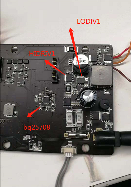
my design board,use bq25708 to charge a 1S3P 18605 battery, now found the charger have very low efficiently,the bq25708 and mos is too hot!
i test use a battery in cc mode. and not have system load
when set charge current (0x14) = 4A, the actual input voltage is 19V 1.1A , the output voltage and charge current i get from bq25708 adc is 4V and 4A , so the efficiently is 16/20.9= 76%
no mater i set charge current (0x14) = 2A, in cc mode or use a low input adapter 13V ,, the result is all the same.
charge 3-5mins, no mater 4A cc mode or 2A cc mode
the bq25708 is 64°
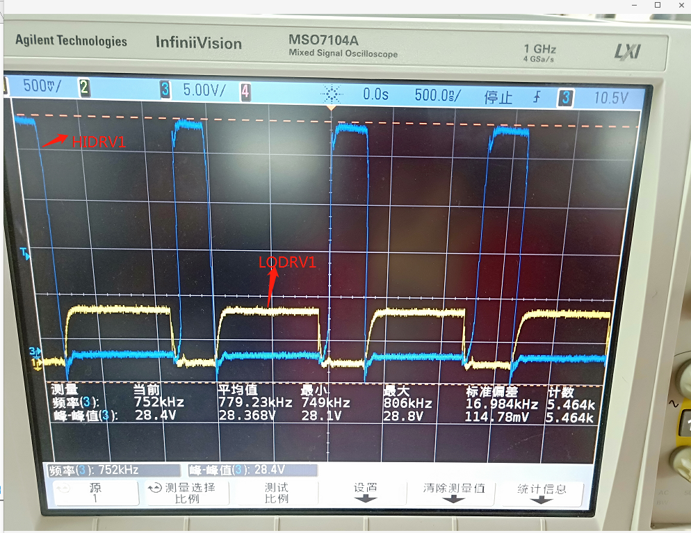
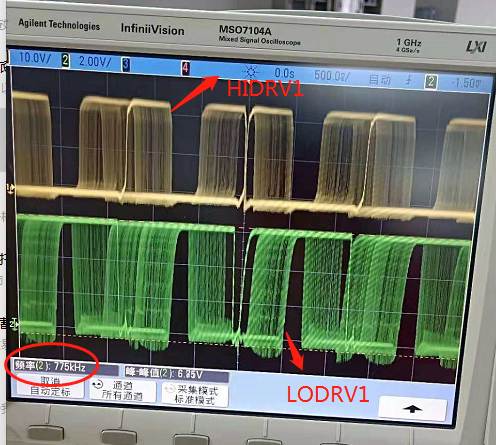
HIDRV1 MOS is 74°
LODRV1 MOS is 64°
2.2UH inductor is 50°
the same condition , the EVM temprature is good.
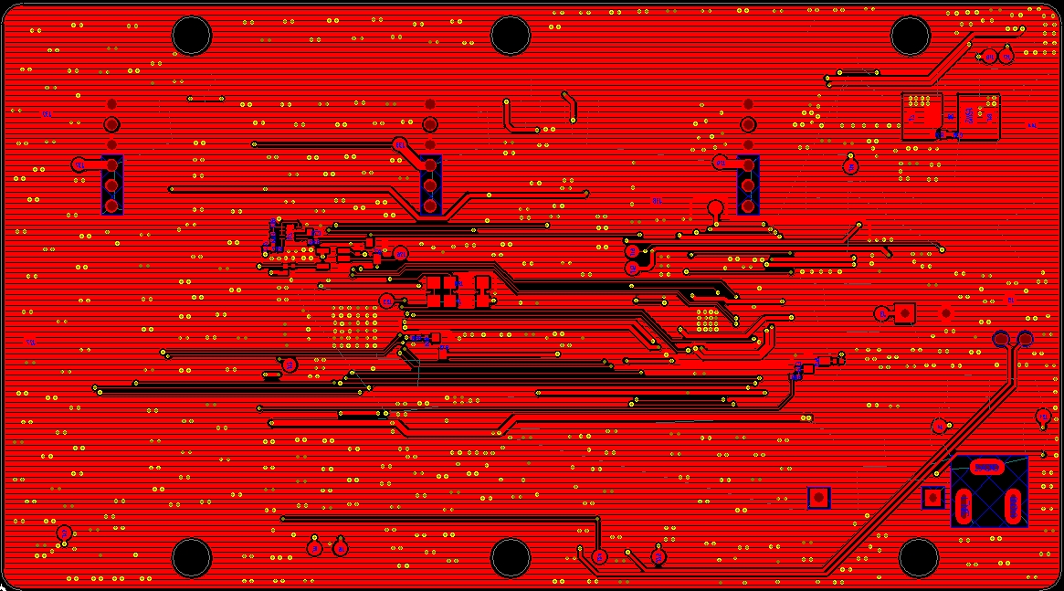
which direction should i to check? is the layout problem? thank you very much