This thread has been locked.

If you have a related question, please click the "Ask a related question" button in the top right corner. The newly created question will be automatically linked to this question.

BQ34Z100-G1: Internal impedance value

Part Number: BQ34Z100-G1
Other Parts Discussed in Thread: BQ34110, BQ34Z100, BQ34Z110, BQ76930

Hello there,

Using the parameters available through the bq34z100-G1, is there a way to estimate the current internal battery impedance without having to open the circuit? I have searched the datasheet and haven't found an impedance read value as such.

I would appreciate all help.

  • Hi Lukasz,

    Impedance Track devices do measure the battery impedance - actually they take several measurements during discharge to build an impedance table since battery impedance is a function of the DOD (depth of discharge). Impedance measurements are taken as part of the algorithm to calculate very accurate SOC (state of charge) and time to empty.

    I assume you want to know the health of the battery due to aging? I have not seen users use the Ra measurements in this way, but it might be possible. You should know that there are multiple conditions that must be satisfied to update the Ra table and your application would need to satisfy these conditions: For example, the device must see good relax periods to get accurate voltage readings, the SOC of the battery needs to see around a 40% change in state of charge to get enough resolution in the Qmax and resistance calculations. If this is a rarely discharged application (like UPS backup battery), this would not be a good device to measure resistance of the battery. The bq34110 hase an End-of-Service feature that would be more suitable for this type of application. See this video below to learn about this feature:
    www.youtube.com/watch

    Best regards,
    Matt
  • Hello Matt, thank you for answer. This is indeed an UPS like application. I have seen the bq34110 device, but it states on its site that it is not recommended for new designs and the bq34z100-G1 is the replacement. Could you explain please?
  • Lukasz,

    I think there may be some confusion. The bq34110 is recommended for new designs. Here is the product page: www.ti.com/.../BQ34110

    I think maybe you looked at the page for the bq34z100 (non-G1)?

    Matt
  • Matt, sorry, I looked at the BQ34Z110 not the BQ34110. Thank you for info, I will check it out.

    So just to summarize, would it be possible to estimate the current impedance somehow during the product life, without having to disconnect the circuitry? this is only for display purposes.

  • Yes, that is possible with the bq34110. However, it is important to keep in mind that the resistance measurements from the bq34110 should be used in a relative way (observe the resistance relative to the initial cell resistance to determine when the battery is ready to be replaced). The resistance measurement by the device will not match the battery manufacturer datasheet resistance because the measurement is at a different point on the frequency spectrum (DC vs. 1 kHz for most manufacturer datasheets).

    The video explains how the feature works in more detail. www.youtube.com/watch

    I'm actually working on a TI Reference design for this type of application, but it will not be available until early next year. Feel free to check back with me then if you think this might be useful.
  • I would definitely benefit from such guide. Looking forward to seeing it. Thank you very much for help.
  • Hello Matt,

    I have one more question regarding the BQ34110 chip. It does say in the data sheet that it is dedicated for UPS backup systems. The thing is that it can accept only 32 A currents. It does say that scaling is possible, but never explained. Also, even 32 A for a shunt resistor is a lot to take. Could you elaborate a bit more?

    Let me add why I am asking: the application under consideration is the one in which a lead acid battery is connected of capacity around 200 AH. The battery serves as a UPS backup but its discharge rate can be even 500 A (the whole battery can discharge within 10 minutes). Is this chip suitable for such application? I cannot imagine using shunt resistor here (although its possible) and was wondering about connecting a galvanically separated sensor to the BQ34110.

  • Hi Lukasz,

    Wow, that is a large discharge current. The BQ34110 does not handle the current directly, so it is not an issue for this device, but I can see how that would be a challenge for the system. I do not know if there is a sense resistor that would handle 500 A and it would need to be sized for the ADC voltage to stay within the +/-125 mV range.
    The BQ34110 does not really have a maximum current since current scaling can be used. Let me know which sensor you end up using.

    Best regards,
    Matt
  • Hello Matt, thanks for answer.

    Even assuming I physically managed to put appropriate sensing method into the system (shunt resistor, current transducer or a hall current sensor IC), the current resolution for the BQ chip (14 bit ADC), for +-500A would be around +-250 mA, which I find very low at situations where the UPS system is being kept charged (99% of the time). Is there any way to force the BQ34110 to operate without measuring current, but only by using rails voltage and learning load?

  • Hi Lukasz,

    For a rarely discharged application, the state-of-charge (SOC) provided by the gauge is not the most useful feature since it will normally be reading 100%. The SOC is the Remaining Capacity / Full Charge Capacity. When a battery ages, the Full Charge Capacity slowly becomes smaller over time. If the battery is always fully charged, the gauge will never have the opportunity to learn and update the Full Charge Capacity and the accuracy will degrade over time. This will be a challenge for all battery gauges because not all of the battery characteristics can be observed from the full charge state.

    That is why for rarely discharged applications, the End-of-Service feature is provided. It is a separate algorithm from the gauging function and monitors the battery cell resistance over time to help identify when a battery should be replaced.

    The gauging feature does use the voltage rails to identify the 100%, 7%, 3%, and empty points. Coulomb counting is needed (using the sense resistor) to track the capacity between these voltage values.

    Best regards,
    Matt
  • Hello Matt, thank you for answer.

    To summarize, could you please answer those questions?

    1. Can the EOS functionality be used without the SoC functionality, or do they have to be used together?
    2. Can the EOS functionality be used when there is no shunt resistor (or other components used for current sensing) in the circuit, but only the learning load resistor?
    3. Using the EOS functionality, is it possible to obtain the impedance/ resistance value of the connected cells?

    Like you said, SoC is not very useful, I agree. It is a good addition, but the current impedance is the most important in this application. The system will be neraly always charged and in rare situations fully discharged in around 10 - 15 minutes. The current will be so high, that I would really like to avoid even trying to measure it, as it would introduce additional costs and/or power losses.

    I would appreciate your further help.

  • ukasz,

    1. Can the EOS functionality be used without the SoC functionality, or do they have to be used together?
      • The SOC can be ignored, so these features do not have to be used together.
    2. Can the EOS functionality be used when there is no shunt resistor (or other components used for current sensing) in the circuit, but only the learning load resistor?
      • There needs to be some kind of current sense. The EOS feature also uses the Current() measurement through the Coulomb counting ADC. You may be able to use a high current capacity hall sensor or a bus bar shunt.

    3. Using the EOS functionality, is it possible to obtain the impedance/ resistance value of the connected cells?
      • Yes, but as I mentioned before these are good relative measurements that will show the change of cell resistance over time. Battery cell impedance is usually specified by the battery manufacturer as resistance at 1kHz. Our devices measure the resistance at DC because that is where the resistance matters most for gauging and for determining the age of the cell.

  • Thank you for answer Matt,
    This cleared thing up. This will be a tough one... I gues a shunt resistor on the RLEN will not do for the internal impedance track algorithm?

  • Yes, I agree there are some challenges with this very high current. I'm looking forward to see how you decide to do the current sense.

    I would love to run some experiments here, but unfortunately I do not have access to very high current equipment and our labs are very strict on safety, so it would be a challenge to get this set up.

    Matt
  • Matt, one more question... I just watched the video you have showed me about the EOS. I understood from it that in order to take advantage of EOS, the system has to be charged/ discharged periodically. But how can the BQ34110 chip tell the charger (whatever external entity it is) to charge the battery now, because it wants to make a learning cycle and discharge it a bit?
  • This type of system requires a host controller. The BQ34110 sets flags in the EOS registers and uses the ALERT pins to notify the host what is happening during the different learning phases and when certain threshold are met. The detailed description of this feature is in Section 2.11 of the BQ34110 Technical Reference Manual - it's around 15 pages.

    Regards,
    Matt
  • Hi Matt,
    Ok, I think everything is clear (at least for now). Thank you very much for your fast help.
  • Hello Matt,

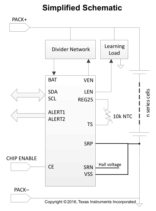
    I have been thinking about this application a bit further. Since as you said, the SoC mechanism is not needed for the EoS mechanism, thus, they can work separately, but the Current() function is still needed, I have came up with the following idea:

    Do you think such changed circuit would work correctly for EoS only? I have removed the shunt resistor from the cells series connection completely, and added it to the discharge load circuit. This way the current will be possible to be measured during controlled discharge. Of course I understand the drawbacks, but just for now, lets assume that during that discharge there will be no other discharge patches available. Would this work as a workaround? Or is the Current() function needed during charging as well?

    Otherwise, I am out of ideas. In this application there will be multiple 12 V batteries connected in series (total voltage of around 400 V) with a common charger for all of the series batteries. Each battery would have one BQ34110 controller attached. Measuring the total current of around 500 A through a shunt resistor (or other sensor) is not really an option here, it will be too expensive..

    I would appreciate your further help.

  • Hi Lukasz,

    This is an interesting idea. I talked with our system engineer about this and he thinks this can work if it can be guaranteed that no "normal" discharge current will start flowing from the load while doing the learning phase. Normally we monitor the current during the learning phase to make sure it stays near the intended level and will abort if current outside of that range is detected.

    The Current() function is used during charging. If you are relying on the bq34110 to indicate full charge completion, this could be important. If not, you will need another way to detect when charging should terminate.

    Regards,
    Matt
  • Hello Matt,
    This was useful info. I will come back with more question after I get further into this. Thank you for your feedback.
  • Hello Matt,

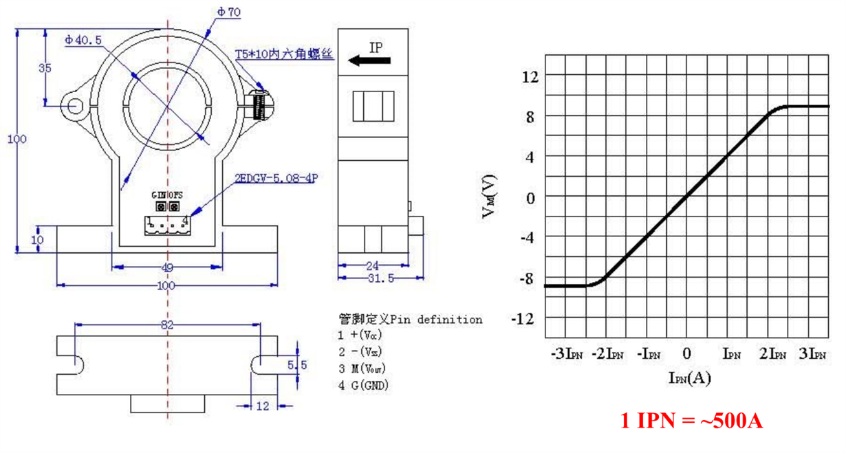
    I have some new information regarding the design. The hack with the shunt resistor in the load circuit might not be necessary after all, since there is a Hall current sensor available for the whole series pack:

    For this application, the sensor would output around 4V when 500A current was detected and -4V for -500A accordingly. Like you mentioned, the input range for the BQ device is +-125mV. In that case a voltage divider would have to be added in order to divide the voltage by 32 (4 / 32 = 0.125). I would then connect the hall sensor output through voltage divider to the SRP pin and ground the SRN pin. Is this approach correct?

    Assuming 14 bit ADC in the BQ34110 device, this should allow to measure current with around 30.05 mA (or 60.1 mA?). Is this enough for the SoC and EOS algorithms? Would appreciate your feedback.

  • Lukasz,

    I do not have experience using a hall sensor with the gauge, but this should work if the voltage across the ADC inputs is correct. I think you would want SRP to connect to VSS and SRN to connect to the voltage input. See this thread (another user was also looking at implementing a hall sensor): e2e.ti.com/.../730105

    The accuracy should be okay for the SoC and EOS algorithms.

    Best regards,
    Matt
  • Hi Matt, thank you for answer.

    I find it a bit confusing about the SRP and SRN connection, since normally the local BQ34110 GND i tied to SRN pin. Is this circuit correct then? Am I missing something?

  • Hi Lukasz,

    Actually, on this device you should be able to connect the hall sensor output to SRP. There is a restriction on the BQ76930 (the other thread for the hall sensor was using this device) and that device expects to connect SRP to VSS. I checked and the BQ34110 does not have this same restriction.

    The BQ34110 can connect VSS to SRP or SRN. There are tradeoffs to both approaches which are discussed at around the 7 minute mark of this video: training.ti.com/bq34110-and-bq34210-q1-battery-gas-gauges-rarely-discharged-applications

    Best regards,
    Matt
  • Hi Matt,
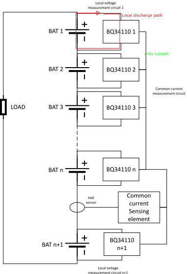
    Ok this is more clear now. I have already seen the video, you linked it before, thanks. Ok, so the last question point is that with the hall sensor, I will not be able to utilize the EOS algorithm, but only SoC. This is due to the fact that there is only one Hall sensor per multiple series connected packs. Each pack has BQ34110 attached. The following block diagram shows the problem:

    In this case an analog switch circuit would be needed to shift between the hall sensor for SoC and shunt resistor attached in series with load for load learning... Can this work?

  • Hi Lukasz,

    This is a challenging configuration. I think it might be best to separate out the SoC and EOS functions. You can use one BQ34110 to monitor the entire stack voltage and the hall sensor and report the SoC. Then you can have one BQ34110 connected to each battery pack, but these cannot monitor SOC because the SRP/SRN pins will need to be connected across a sense resistor to monitor the learning load. You would need to control when the learning phase starts to ensure that the normal discharge/charge currents are not flowing through the system load.

    I think connecting the hall sensor output to multiple BQ34110 devices across the board would introduce voltage offsets that would be difficult to deal with.

    Best regards,
    Matt
  • Hi Matt, Thank you for answer.

    Regarding the common voltage to current signal from hall sensor to multiple Bq- I think that adding a voltage follower with a low output impedance would solve this problem, but I agree that this is still a bit risky. The solution  proposed is a lot "cleaner". In that case however, there will be no SoC of individual packs, but the question is is that really necessary? Also going down from over 400V to around 4V for the Bq regin seems more problematic, but doable. Could also power the device from a single pack (just for the same of regin, not the whole system voltage). What do you think?

  • Lukasz,

    I think that's a good idea for REGIN since this just needs to be in the correct range to power the LDO.
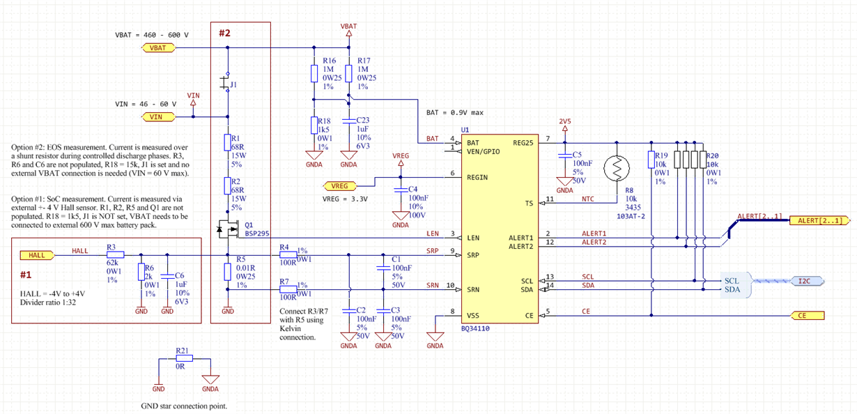
  • Hello  

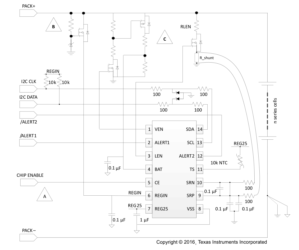
    So I have some early version of the BQ34110 circuit:

    I would like to know your opinion about it. I have tried to introduce all of the solutions we have discussed about. So, there would be 2 mounting options for this circuit:

    1. SoC measurement. EOS is not measured.
    2. EOS measurement. SoC is not measured.

    In the design there are 10 series packs. Each pack is 60V max, so the whole string is 600 V. Each module (pack) has an EOS measuring BQ34110 and for the whole string there is 1 SoC measuring BQ34110.

    I would appreciate your thoughts on this solution.

  • Hi Lukasz,

    This looks correct to me based on the unique application needs we have discussed.

    Best regards,
    Matt
  • Hi Matt,
    Thank you for the answer and your time you have put into this case. I will let you know the results.