This thread has been locked.
If you have a related question, please click the "Ask a related question" button in the top right corner. The newly created question will be automatically linked to this question.
Part Number: TL431A
Hi Team,
There is TINA-TI AC Reference Design as the following.
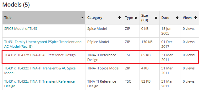
I download the design and tried changing schematic as the following (VKA=5V, IKA=50mA, CL=20nF) then run simulation, however phase margin is around -20deg (unstable).
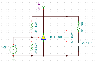
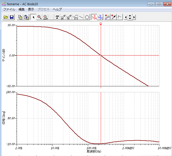
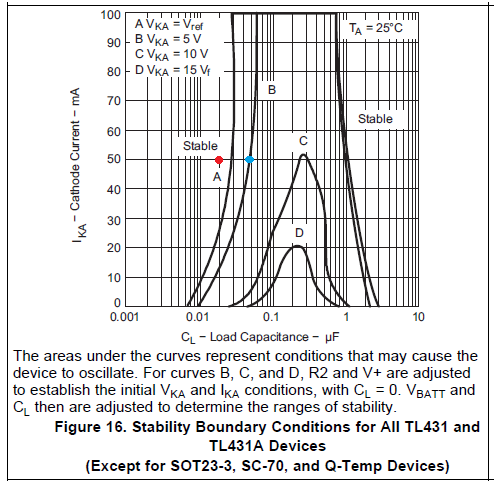
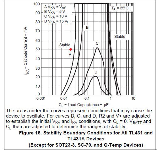
I believe the schematic is stable condition because left side of curve B in Figure 16.
Should we consider AC simulation can't be used for TL431A?
If my simulation is incorrect, your advice is really appreciated.
Best Regards,
Yaita
Hi Marco-san,
Thank you for your kind support!
>I recommend staying at least half a decade to a decade away from the boundary region. I would not use 20nF, it is to close to the border.
It is blue dot when VKA=5V, IKA=50mA and CL is around 50nF on B curve.
I understand it is recommended set to CL less than 10nF in this case.
Is my undersytanding correct?
Best Regards,
Yaita
Hi Yaita,
Yes 10nF is better. If you are going to use this TL431 in extreme temperature deviations, then I would decrease the value further. Temperature does affect the stability of the device.
Also why is the bias current of the TL431 50mA? that is a lot of power being used. Can I propose to use figure 34 to have a better Ika? If you decide to use figure 34, I would highly recommend to use the TL431LI as the stability region is much better.
-Marcoo