A related question is a question created from another question. When the related question is created, it will be automatically linked to the original question.
If you have a related question, please click the "Ask a related question" button in the top right corner. The newly created question will be automatically linked to this question.
There are faults to cause shutdown. Can you follow the datasheet to check each fault condition to find which fault triggers this shutdown? You can search "fault" using your PDF reader, to find fault and then check your board to see if that is the fault triggers the shutdown.
Can you change to a new device to see if the issue is solved?
Do you have an EVM and can you compare your circuit to the EVM to see anything different? Did you evaluate the EVM and see similar problem?Can you remove the problem device from your board and put to the EVM to see if same fault happening?
I had changed the new device, and it still happens.
We had followed the layout guideline.
I had replaced around components with new ones.
I had confirmed that device didn't be wrong.
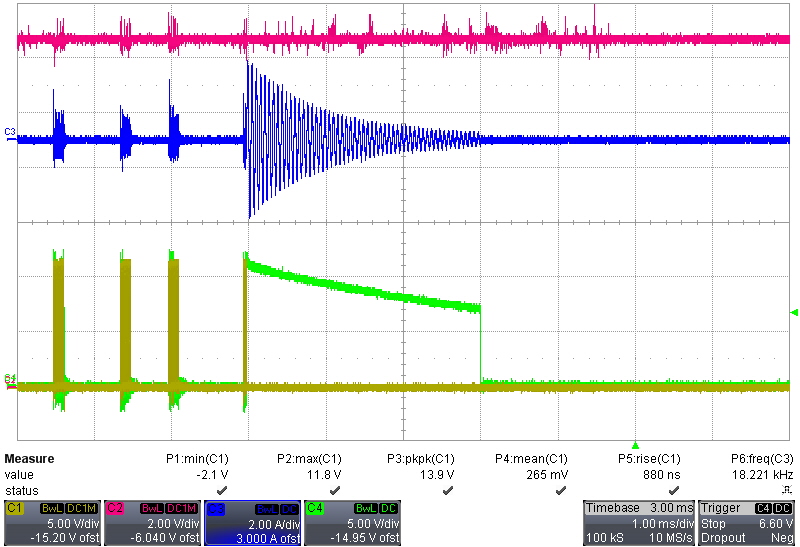
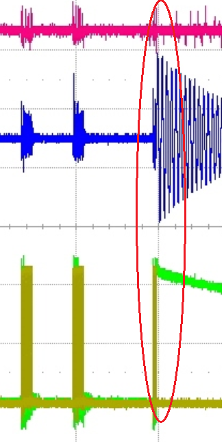
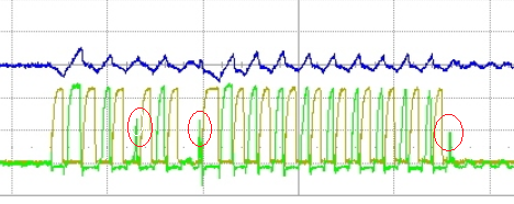
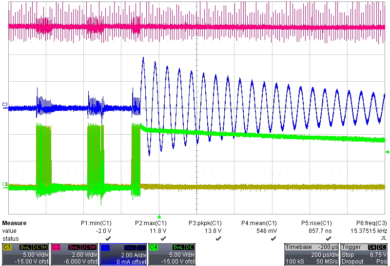
Can you zoom in the red circled area with a few switching cycles before stop switching so we can understand what happening? Your current 1ms scale is not good to tell what happening in detail.
The waveform shows possibly RVCC is nearby UVLO OFF so turn off both drivers. RVCC off at typical 7V. Your waveform shows that from either driver output. The waveform still needs further zoom-in and with better resolution. Have you checked RVCC as I asked before? If RVCC ok, please find out why both drivers show around 7V or even < 7V?
I am asking you to show better waveform resolution and to show if the wide pulse is only for this cycle or present on other cycles. Did you check RVCC to see if RVCC under-voltage protection?
I am just asking a question if the wide pulse is a hint of the issue. I do not know the issue root cause but I am showing you how to do the trouble shooting.
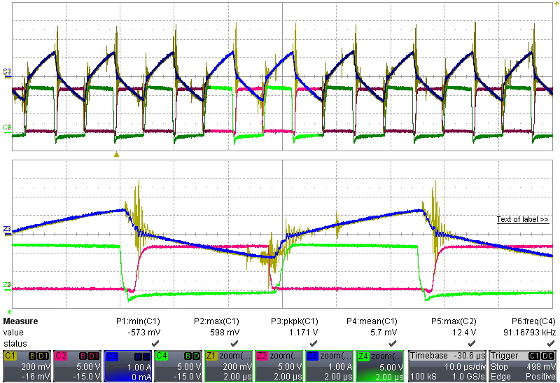
Please show RVCC together with both driver pulses at switching stop area, that is add RVCC into the below waveform you showed. Please also show better resolution for the waveform since the waveform shows both driver outputs are near 7V which is nearby RVCC UVLO OFF. Please use better time scale so we can tell what is RVCC and if RVCC is ok why both drivers outputs are at 7V nearby. Please provide these so we can see if any hints.
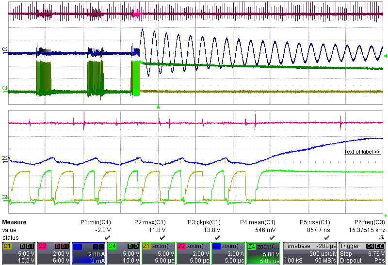
Please also zoom in the below which is copied from your 1ms/div scale. We need to see if the wide pulse is always there or just there before switching stops. It looks you can use 200us/div to re-capture the waveform. The purpose is to check if the wide pulse is always there - so if 100us/div cannot make it clear, please use use zoom-in to show. Please add RVCC to the waveform capture. We need to confirm RVCC ok.
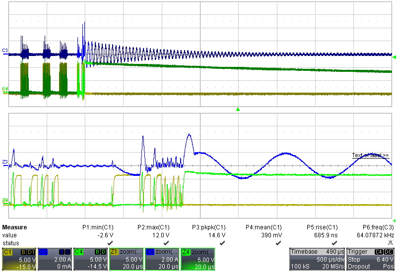
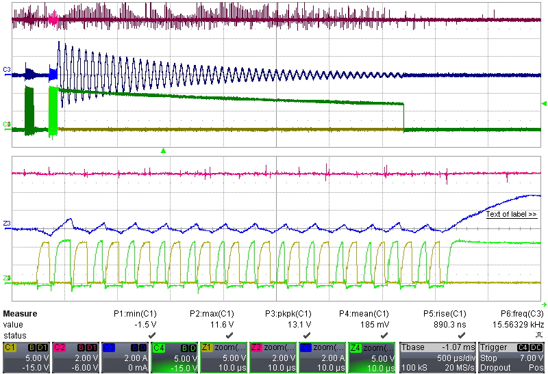
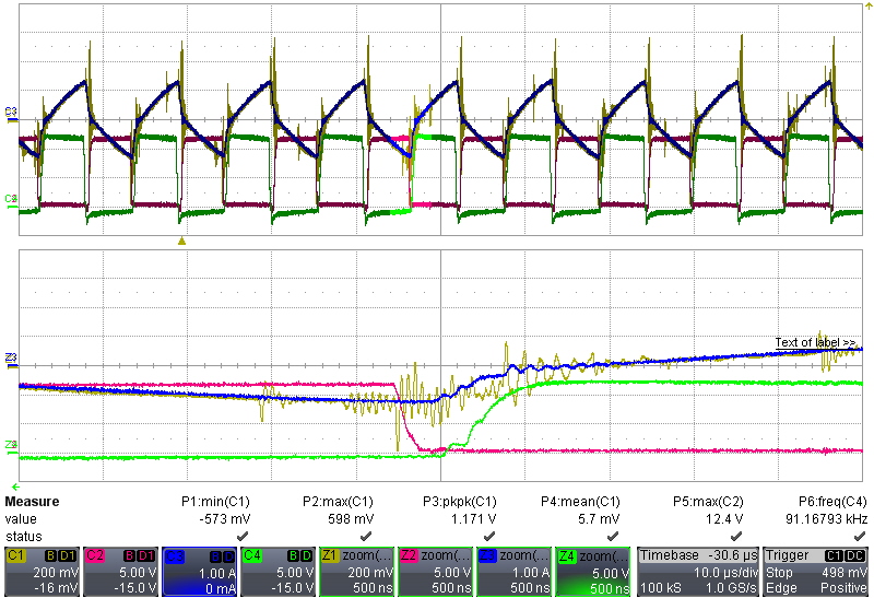
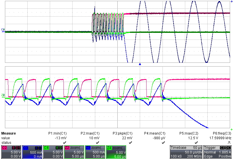
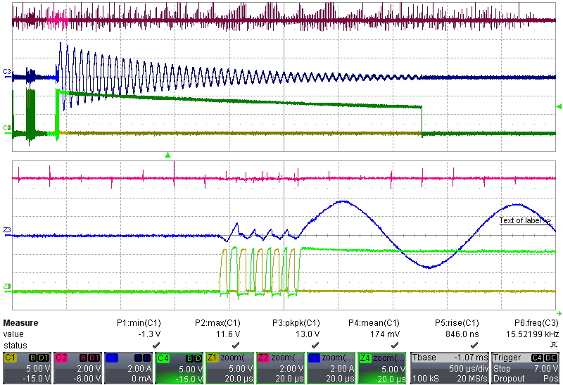
This time the waveforms are different from the last time - can you capture the same waveforms at the same operation condition? Is this time what you show actually a normal power off? But anyway, please show capture the waveforms at the same conditions as above.
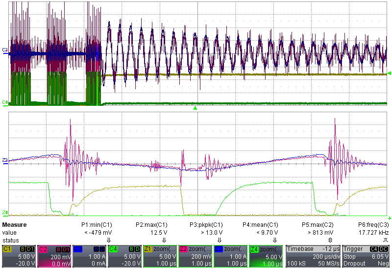
The one before with wide pulse and with pulse peak < 7V. The one after shows regular without wide pulse and with pulse peak >10V. I need to see the waveform at condition of the last time with better resolution. You need to show the waveforms consistent in order to help you. Please provide the waveforms I am asking.
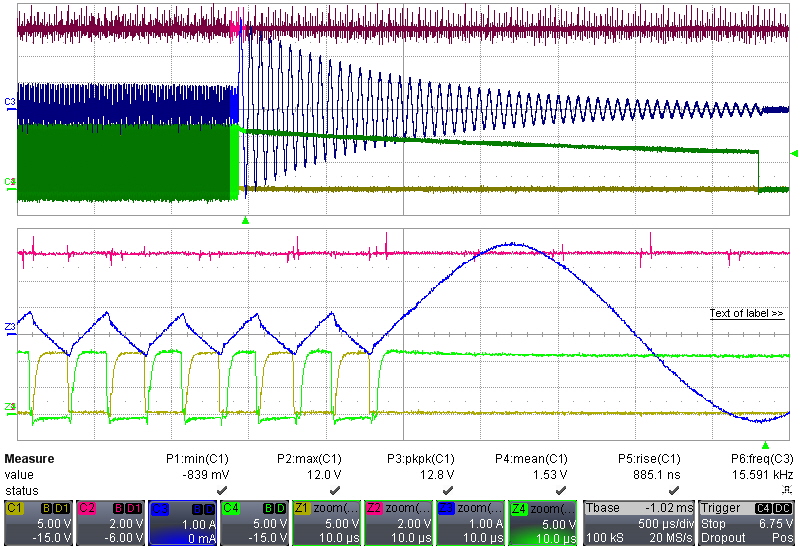
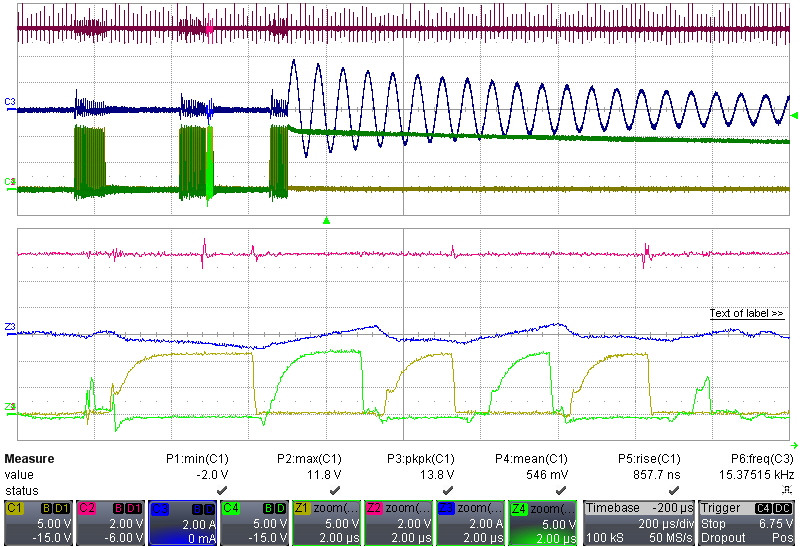
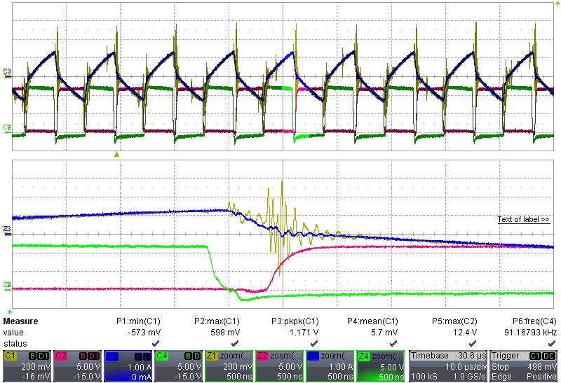
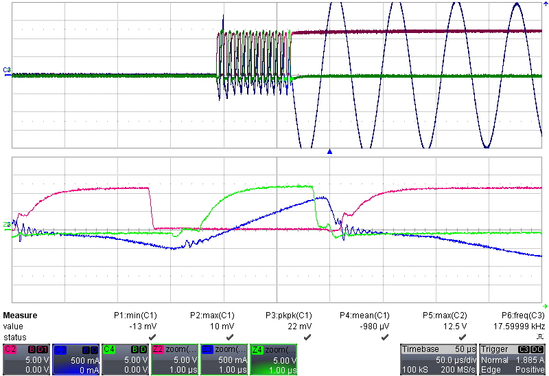
Add RVCC into the below with your oscilloscope horizontal scale 20us/div, or 50us/div. The below waveforms do not show driver peak clearly. I need to know how much peak voltage on each drive outputs as well as RVCC at the same time.
Please add RVCC into the below with your oscilloscope horizontal scale 20us/div, or 50us/div. The below waveforms do not show driver peak clearly. I need to know how much peak voltage on each drive outputs as well as RVCC at the same time.
I can't capture the same waveform now. But its condition is the same.
Don't focus on before waveform. Can you use the last waveform to solve it? It has being the same situation and I has checked that no protection was happened.
My problem is simple what it had been latched. The Vcc isn't UVLO.
If you don't know the problem, can change anyone ?
I cannot change this thread to anyone else. I need you to provide consistent waveforms. If you cannot, is it possible your board has soldering issues? Otherwise why you cannot get your test waveforms repeat?
Besides, how the VCC is biased in your design? Can you provide your schematics for review?
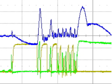
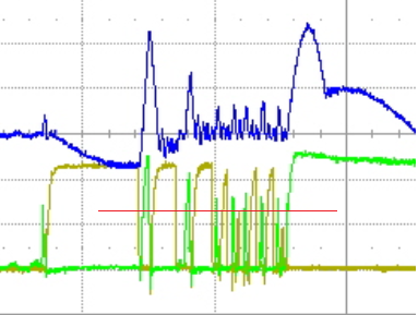
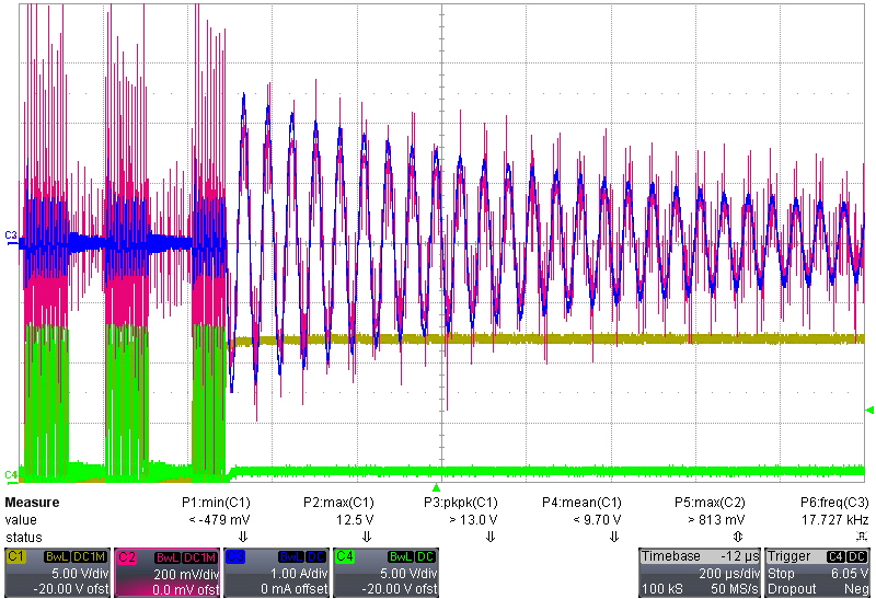
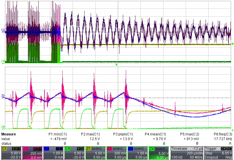
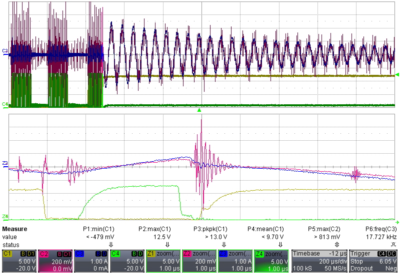
The below is based on your new waveforms The three red circled areas with pulse peak < 7V. Can you zoom in these area with RVCC? I need to know why these three areas pulse peak that low.
I need to confirm with you:
1) You use an external power supply to bias UCC256303, right?
2) Please provide the operation conditions when the switching stop issue occurred, such as input voltage, output load, etc.
3) Your schematics show you are using a load sharing device, so please let me know when the issue occurred, is UCC39002 in operation with the other converter, or the issue happened without parallel with the other converter?
4) The schematics show LLC ENB, can you remove Q103 and re-test to see the issue still present, so to exclude pulling down falsely by Q103?
1) You use an external power supply to bias UCC256303, right? YES 2) Please provide the operation conditions when the switching stop issue occurred, such as input voltage, output load, etc.
It's random, but it often happens at light load . if it's not at skip mode, it sometimes happens.
3) Your schematics show you are using a load sharing device, so please let me know when the issue occurred, is UCC39002 in operation with the other converter, or the issue happened without parallel with the other converter?
I used to remove it ,and the issue happened .
at single power
4) The schematics show LLC ENB, can you remove Q103 and re-test to see the issue still present, so to exclude pulling down falsely by Q103?
I used to try to do the way ,but still shut-down .
2) For this question, can you show waveforms with output voltage, both drivers, and RVCC, at fault happening, with single converter in operation, UCC39002 removed, Q103 removed.
3) So your test is on one converter and not paralleled with the other converter, right? Also, you did test with removed UCC39002, right?
4) So your test is with Q103 removed, right?
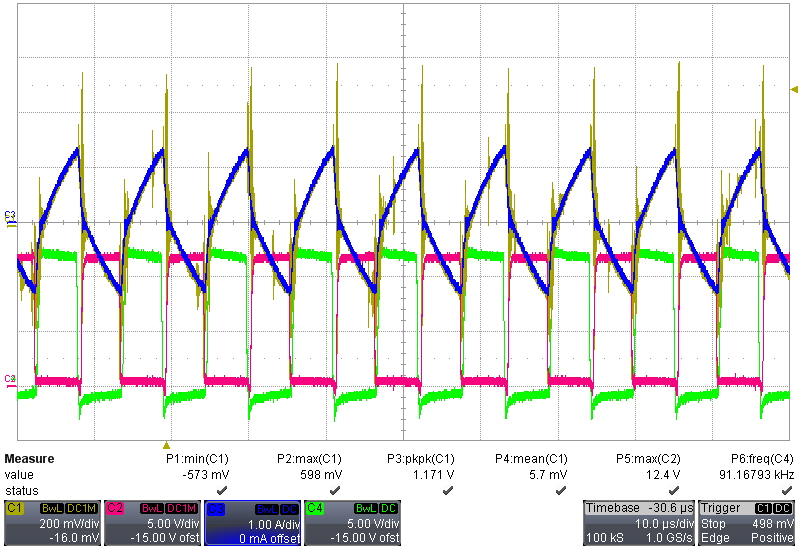
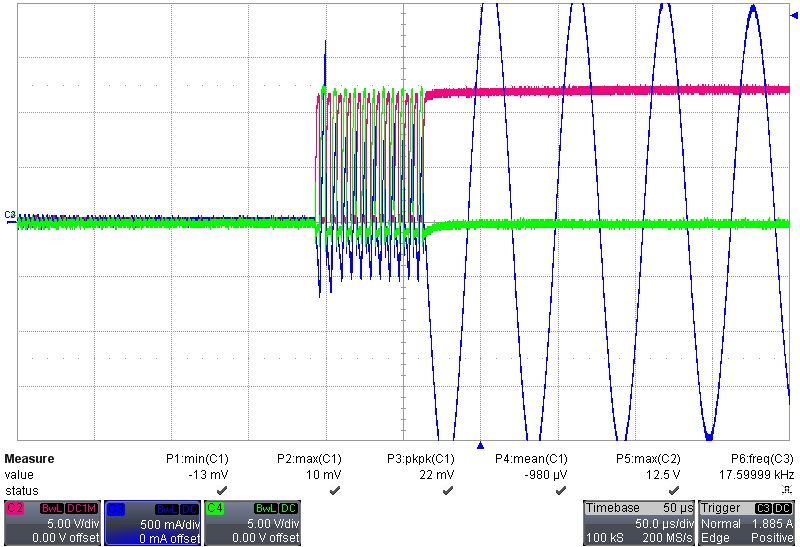
As these are confirmed, one possible reason we can think is ISNS pin signal gets multiple zero crossings which can confuse the internal function. Can you probe ISNS zero crossings along with LO/HO latch off? If you do see multiple zero crossings, you can try to increase C126 in your design (may also need increase a bit of C114) to eliminate the multiple zero crossings to see if the issues can be resolved.
Yes, increase the capacitance on ISNS pin, that is actually C110. If ISNS pin signal has multiple zero crossings, the similar issue to what you have can happen on our test. If ISNS signal is very noisy, it is likely there are multiple zero crossings. ISNS signal has to be clean to exclude the root cause from ISNS for your issue.
if ISNS does not have multiple zero crossings, the issue you see can be eliminated. So the key point is eliminate multiple zero crossings. Other noises on ISNS are not considered for this issue you see.
If increase capacitance cannot be sure to eliminate ISNS signal multiple zero crossings, the next that can be is to review the layout to see it can be improved. The ISNS should not have multiple zero crossings which needs to confirm.
Can you show your ISNS waveform without multiple zero crossings? The ISNS multiple zero crossings is what we know for this issue. Other thing you may want to check is your dc input voltage - but it should be good since the operation was ok when the issue present.


