This thread has been locked.

If you have a related question, please click the "Ask a related question" button in the top right corner. The newly created question will be automatically linked to this question.

UCC256301: Questions about blue stone HV pin

Part Number: UCC256301
Other Parts Discussed in Thread: UCC25630-1EVM-291,

Dear sir/ madam,

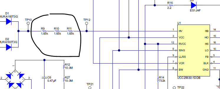
Regarding to  UCC25630X HV pin.

1. Why three resistor at HV pin?  

2. is one 5k resistor here okay?

3. how to test the X capacitor discharging waveform with EVM board.?

i failed to test the result shown on UCC25630X EVM user guide.

what is test is the voltage of x cap(C3,C4 on the EVM )  go to zero immediately when the AC power turn off.

  • Hello Shubiao,

    Thank you for your interest in the UCC256301 and its EVM (UCC25630-1EVM-291).

    For your questions 1 and 2: The 5 Kohm value for this location is specified in section 8.2.2.15 in the UCC256301 datasheet. The EVM uses three series-connected surface-mount resistors to implement this. All parts have some limited voltage-withstand capability. Because these parts are SMD, they the 1206-size is chosen because this package size has a 200-V limiting element voltage rating. Three of them in series provides sufficient margin to the anticipated peak high voltage from the "universal" line (85 Vac to 264 Vac).

    A single resistor can be used here provided that it also has sufficient voltage-withstand rating for what is to be applied across its terminals.

    For your question 3: The X-cap waveform may be viewed using a high-voltage differential probe placed at test-points TP3 and TP4 on the EVM. schematic diagram. The waveform of Figure 13 in the EVM User Guide was obtained by measuring at TP4 to TP3 with 264 Vac applied to J1. The oscilloscope was set to trigger on a signal occurring after about 76 ms of no-signal. Then the AC input was shut off for a duration of about 1.4 seconds to capture the X-cap discharge timing.

    The X-cap is not immediately discharged when AC is removed. Rather the IC conducts periodic tests to determine if the AC line is present or not and when satisfied that the line is gone, then discharges the cap with a controlled current (about 11mA). This test pattern is described in section 7.4.3 of the UCC256301 datasheet.

    I hope this answers your questions.

    Regards,
    Ulrich
  • Thanks Ulrich,

    i will follow you measuring method to capture the X capacitor discharging waveform and update the waveform in next week.

    BRs, Shubiao
  • Hello Shubiao,

    Just checking in to see how things are going.
    Have you been able to make the discharge measurement?
    Is this issue resolved and can be closed, or does it need more support?

    Regards,
    ulrich
  • Happy new year,Ulrich,

    i will update the wave form i tested this evening.
    by the way, what's the function of RV1, connected in parallel with X-cap.

    Regards!
    Shubiao
  • Hello Shubiao,

    Sorry for my delayed response. RV1 is a Metal Oxide Varistor (MOV) which is commonly placed differentially across the input line of AC-connected power supplies. It behaves like a crude bi-directional zener diode or transient voltage suppressor (TVS). Its purpose is to clamp differential mode surges and impulses and protect downstream components from overvoltages to survivable levels.

    It is included in this EVM design mainly for consistency with almost all other off-line designs, although the AC portion of this EVM has an "abbreviated" function simply to demonstrate the X-Cap discharge feature of the IC, but not power the actual LLC power stage.

    Regards,
    Ulrich