This thread has been locked.

If you have a related question, please click the "Ask a related question" button in the top right corner. The newly created question will be automatically linked to this question.

CSD97395Q4M: CSD97395Q4M can support Buck-boost circuit?

Part Number: CSD97395Q4M

Hi ti team,

       Could you pls help us check if CSD97395Q4M can support buck-boost circuit? 

if give PWM,skip always high level,then the control mosfet driver can be always high?

1, test condition:Vin 12V,Vout 3.3V/15W

 no Vout 3.3V output

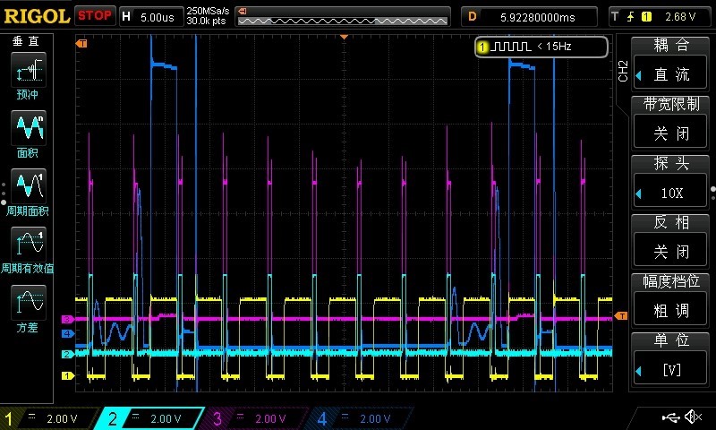
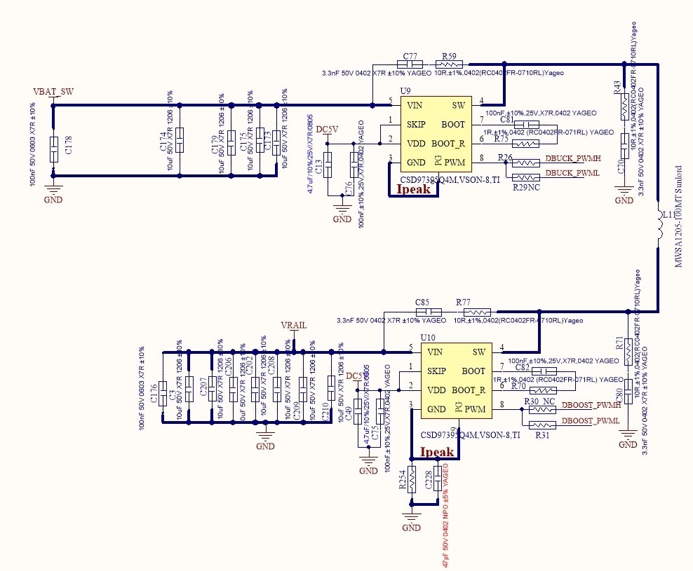
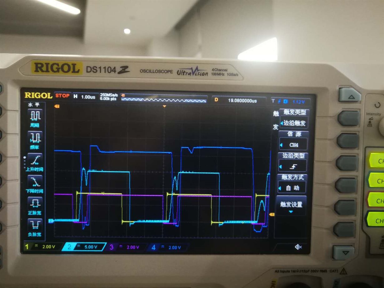
2, SCH as below and test wave form as below

1Ch,2Ch,3ch,4ch as U9PWM,U10PWM,U10SW,U9SW

  • Hi Jimmy,

    The boot cap is charged when low-side FET is on.
    If PWM is always high, the boot cap can not be charged. The boot cap voltage will decay and highs-side FET will be off after some time.

    Thanks
    Qian
  • Hi Qian Chen,

          thanks for your reply,If this could confirm  CSD97395Q4M can't support Buck-boost circuit? as above circuit.thanks!

  • Hi Jimmy,

    As I explained, CSD97395Q4M can not keep high-side FET always on because boot cap voltage for high-side gate drive will decap.
    This could be a problem for U9 because the high-side FET of U9 should keep on in boost mode.

    Thanks
    Qian
  • Qian chen,

          Could you pls help check below question and advise?thanks!

          After confirmation,Customer Make this circuit  in Buck-boost mode. 

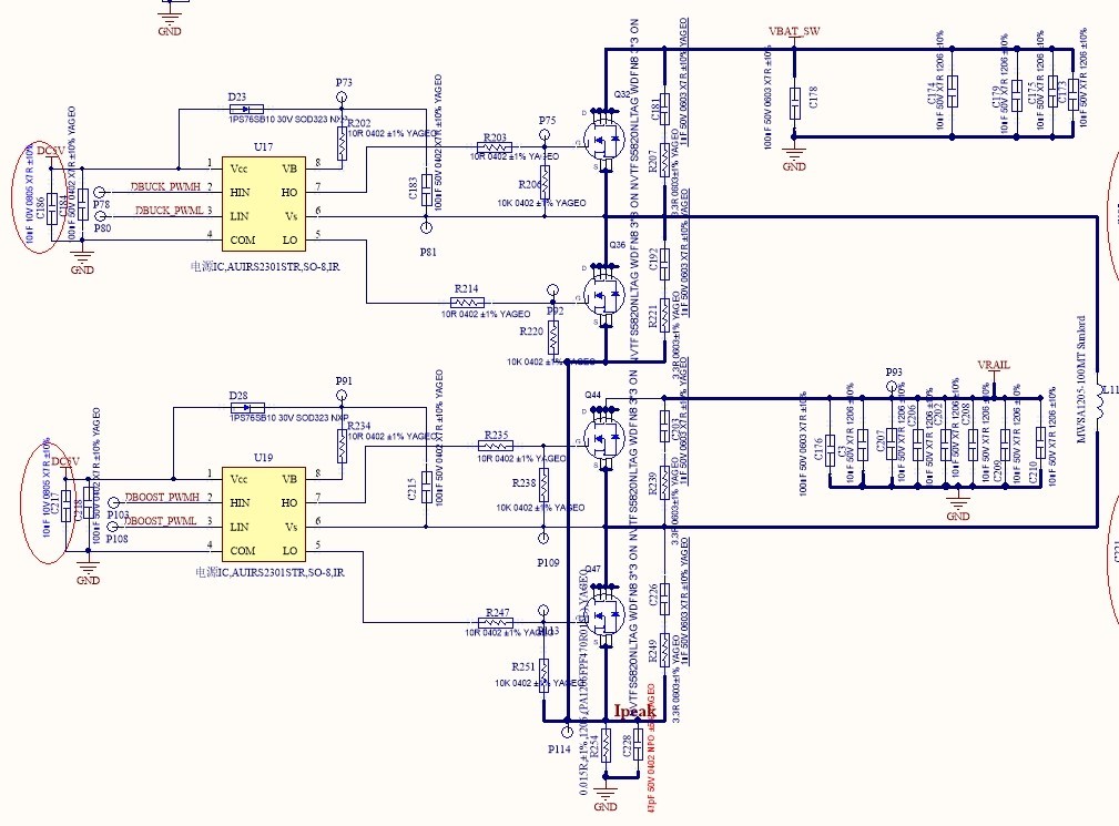
          Customers with previous discrete devices IRS2301 and Mosfet can work normally, CSD97395 to replace IRS2301 and mosfet.

    then Software drive unchanged (CSD97395Q4M only used DBuck_PWMH and DBOOST_PWMH, No used DBuck_PWML and DBOOST_PWML)

    CSD97395 used the same software not work.

          What can be done to improve it work normal  used the same software? 

    The follow-up volume of this project is 500k/Y, this project used in car wireless charger.

    Old sch as below

  • Hi Jimmy,

    I double checked the new schematic and test waveform, looks like U9SW does not follow U9PWM.
    We will have someone who is more familiar with this part to support you after Jan 1st.

    Thanks
    Qian
  • Hi Jimmy,

    In the discrete case you said only DBuck_PWMH and DBoost_PWMH are used.  If that is the case, the low side FET of each half bridge is never turned on.  Only the body diode is used.  For CSD97395Q4M the behavior will be different.  When PWM is low, the high side FET will turn off just as in the discrete case, but the low side FET will turn on as well.  I think this is why you are seeing different behavior between the two circuits.

    Regards,

    Evan

  • Evan,

         The discrete case  IRS2301 used 4PWM :DBuck_PWMH, DBOOST_PWMH and DBuck_PWML, DBOOST_PWML

         The  CSD97395Q4M only used Two PWM: DBuck_PWMH, DBOOST_PWMH  (software no changed)

    then

        Could you help us give some advice to let CSD97395Q4M (used DBuck_PWMH, DBOOST_PWMH) work in Buck-boost normal ?

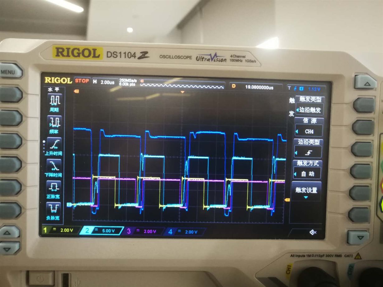
    Give the discret case IRS2301 normal waveform for ref

    Input 15V,output 10V/5W

    Ch1:U17 DBuck_PWMH

    CH2:U17 SW

    CH3:U19 DBOOST_PWMH

    CH4:U19 SW

  • Hi Jimmy,

    Thank you for the waveforms, I think I understand now. I think the problem may be the GND reference for the power stages. Since the driver is built into the power stage in the CSD97395Q4M, the GND pins need to be connected to the same ground as your PWM input. Since it is floated in your application, the PWM level with respect to the IC GND is not correct and U9 is not responding as expected. This can be verified by measuring PWM with respect to the power stage GND (not your system GND). If this is the case, this device is probably not a good fit for this application.

    Regards,
    Evan
  • Hi ti team,

    Short the current sensor and provide PWM and GND two line to CSD97395Q4M,The problem remains the same.

    If add PWM pull down 10K resistor, The problem is solved

    So, Could you pls help check if have other problems for PWM Pin add Pull down 10K resistor? your refer design no this .


    thanks!
  • Hi Jimmy,

    There should be no problem with adding a 10K pull down resistor to PWM.  PWM internally has high impedance pull up/down resistors to set the PWM to tri-state (the off state) when PWM is not driven.  By adding this external pull down you are over-riding that default behavior so that the default condition will now be PWM low (LS FET on).  As long as your PWM controller can over-drive the 10K resistor and you don't have a need to tri-state PWM this can be a workable solution.

    Regards,

    Evan