- Ask a related questionWhat is a related question?A related question is a question created from another question. When the related question is created, it will be automatically linked to the original question.
Dear TI,
I implemented a design based on a WebBench tool and it quite nearly works great except the current output is 15% low.
This is my design.
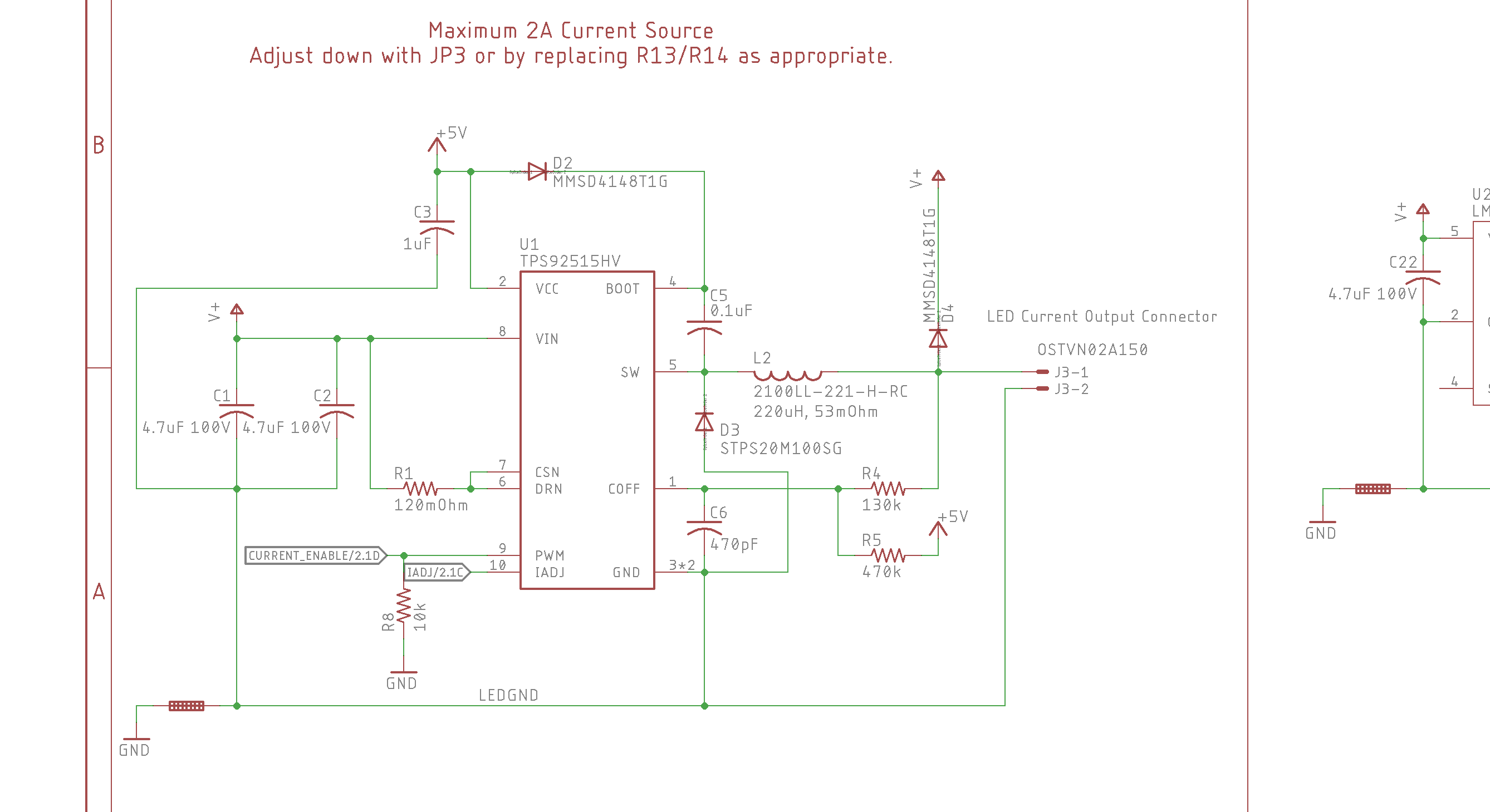
I made a few modifications from the Web Bench design -- I increased the inductor to 220uH and eliminated the output capacitor due to my need to turn it on and off at 40Hz (a bit slow and allows Coff to drop too low if I remember right). I also added R5 to assist with keeping it running, added IADJ as an external input (2.4V for my test) and I added a flyback diode for the LED wiring inductance.
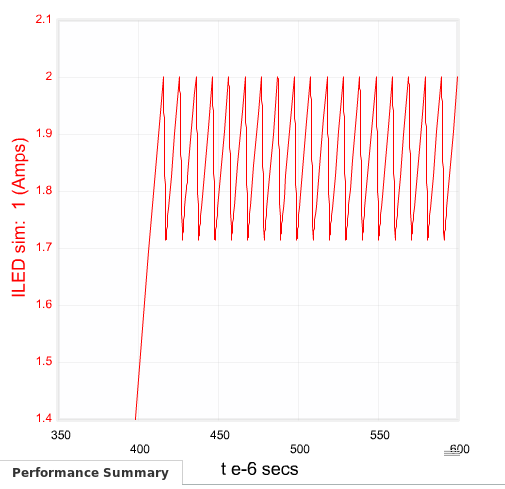
The current setpoint should be 2A with a 113mohm resistor, so I'd have expected it to be a bit low, but I'm measuring 1.715A instead of 2A. Do I need to install a smaller Rsense, or is there something else limiting the output current? I tried updated the parts in WebBench (setting the inductor larger and making the output capacitor 1pF) but varying the sense resistor didn't seem to change the operational value claiming a 2A average LED current. I tried forcing it to use an 80mohm resistor and the simulation operational values just didn't change at all. I suspect it isn't properly modeling the updated inductor and capacitor since I know the inductor will see more ripple current.
That said, I manually did the Rsense calculation using the Web Bench estimated inductor current ripple and it only suggested 113mohm, so I'm kind of confused. If the relationship between Rsense and Iout is linear, I'd expect to only need a 102mohm Rsense. But maybe C6 is the wrong size or something, or perhaps adding R5 shifted the math?
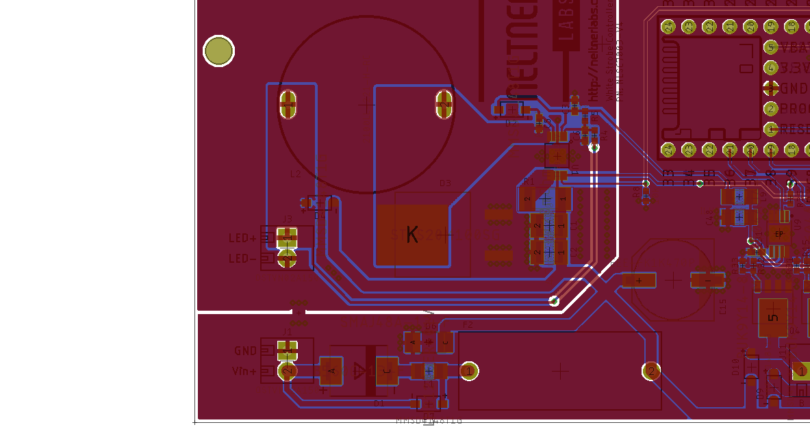
I have the board implemented here, so happy to try any recommended modifications.