This thread has been locked.

If you have a related question, please click the "Ask a related question" button in the top right corner. The newly created question will be automatically linked to this question.

TPS65133: -5 V inverting buck boost converter is not working

Part Number: TPS65133

Hi,

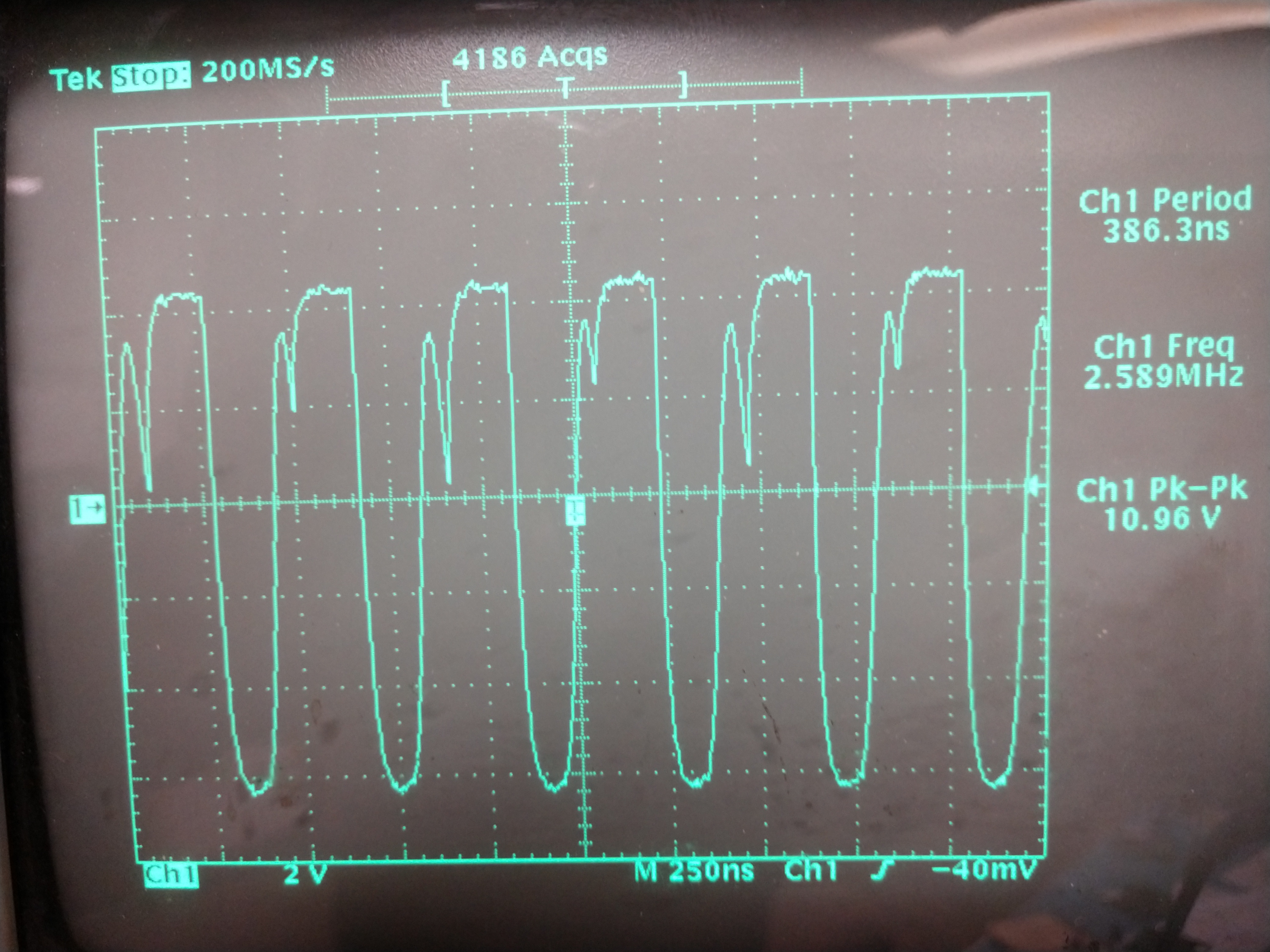
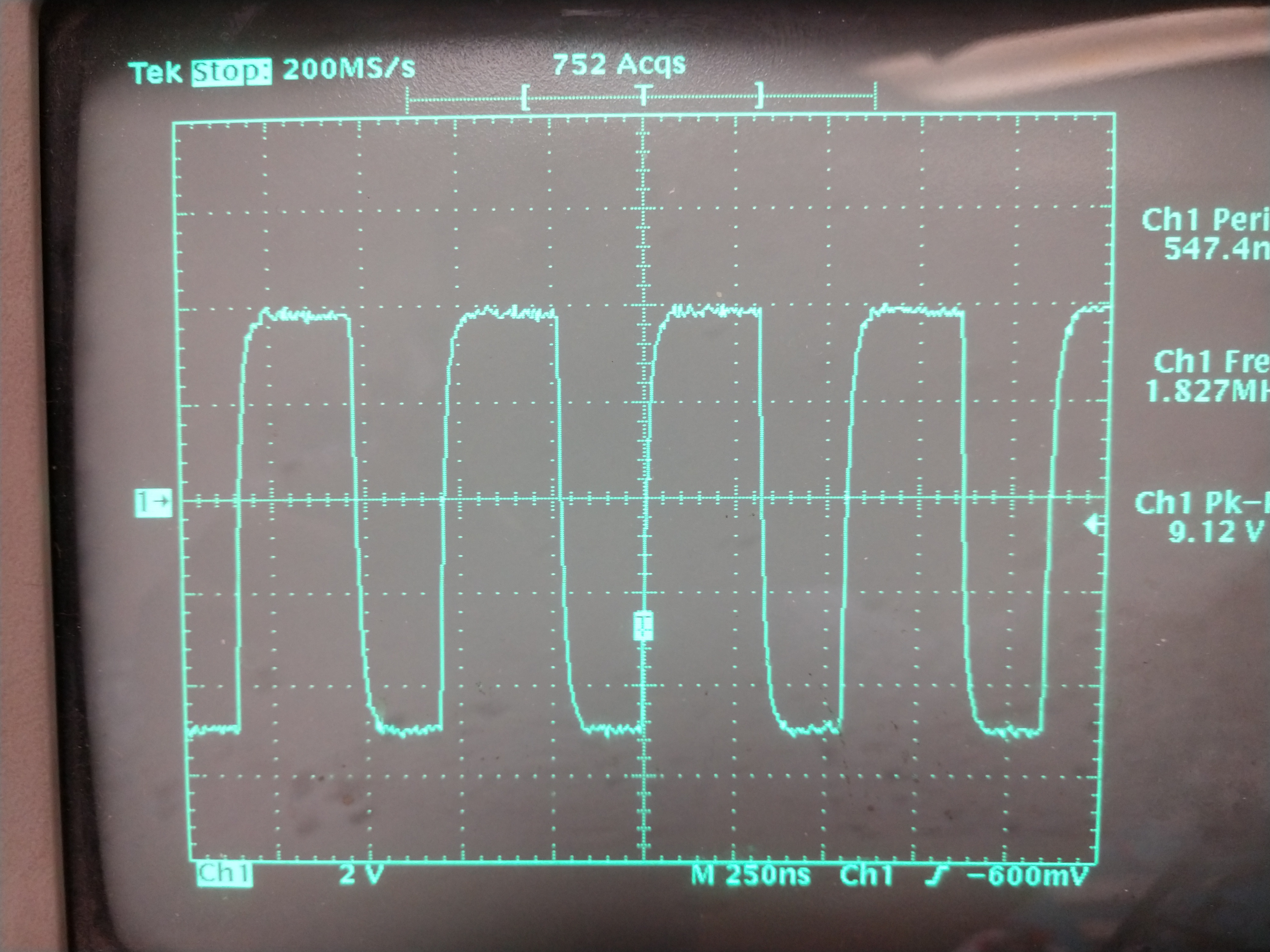
My input is a Lion Battery, the Vpos shows +5V correctly but the -5V is showing 0.6V.

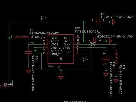
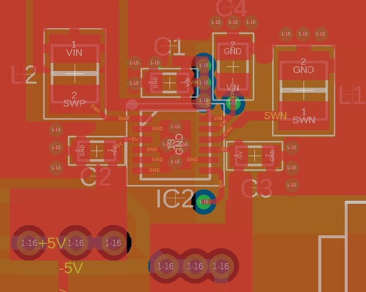
Below is a layout of the part.

I am using 1239AS-H-4R7M as my L1 and L2 inductors.

Could you let have a look and let me know?

  • Hi,

    I have notified our expert regarding this topic. Please expect a response by 1/31/19.

    Thanks,
    Aaron
  • Thanks, attaching a screensot of what is happening on L1 which is connected to the SWN pin.

    L2 is a square wave at 1.7 Mhz going from 0 to 5 V on the SWP pin.

  • Hello,

    Can you please attach schematics of your design? Also, I am not able to access the layout that you mentioned in your post. Once I get the schematics/layout, I will review to see if I can find the reason as to why the inverting converter is not working.

    Kind Regards,
    Liaqat
  • Hi,

    I am experiencing the same issue; +5V good, -5V showing 0.6V. I followed the recommended layout on the datasheet.

  • Please find attached the schematics and layout

  • Hello again,

    Thank you for attaching your schematics and layout. I reviewed these and do not see anything that should cause VNEG to not come up at all. If it was something like an overload condition at VNEG, the device would shut down and and you would not see even the positive supply at +5V.
    Not sure if you have scope probed the VNEG output at startup. Does the VNEG output come up even briefly at power up?
    Is this happening on more than one board assembly?
    Unfortunately, I don't have any solid clues as to why the VNEG is not coming up but I will be willing to take a look at your board design in the lab if you are able to send one to me.
    Kind Regards,
    Liaqat
  • Hi,

    My design here is nearly identical to the design of your other customer who submitted the files (essentially the recommended design from the datasheet). I've tested several boards all with the same result. 5 V good Vneg reading about 0.66 V.  I looked at the switching frequency at the V neg  inductor on my design and it was essentially not running.  I don't have a scope capture to post at the moment but can do so later in the week if that provides any insight. Would it help if i provide the date codes on the chips.

  • Hello,
    In the case of other customer switching node waveform has approx. correct frequency and in your case, it seems that negative switch node is not switching at all. What would help in further debug is if I can get one of these boards and look at it in the lab. In addition, you can also provide lot code (just provide all of the text markings on the device line by line). It appears that you are in the US so if you can provide your e-mail via PM, I can send you my shipping address. Thank you.

    Kind Regards,
    Liaqat
  • Hi,

    Thanks for taking a  look at this, I think there was some soldering issue on the board near the -5 side of it.

    The issue got resolved when I soldered a New chip. The waveform at the SWN pin looks better compared to the previous posted waveform.

    Please do let me know if you still want to take a look at the boards


    Thanks

    Anand

  • Hi Liaqat,

    The markings on the device are SHY TI 391 APFN,

    I have attached some pictures of what i am seeing on the negative switching node.~ 35kHz

    On the positive side i am seeing 1,7Mhz.

  • Hello,

    As you saw from the OPs last response, the issue with that design was related to board assembly. Since you are experiencing similar symptoms of 0.6V on VNEG, it could potentially be similar assembly issue. Beyond that, I am not sure of the cause not having VNEG supply come up. If assembly issues are ruled out, I will be happy to take a look at one of your boards in the lab if you are able to send one.

    Kind Regards,
    Liaqat