This thread has been locked.

If you have a related question, please click the "Ask a related question" button in the top right corner. The newly created question will be automatically linked to this question.

BQ76PL455A-Q1: BAT0 in EV1402EVM

Part Number: BQ76PL455A-Q1
Other Parts Discussed in Thread: EM1402EVM, BQ76PL455A, BQ76PL455EVM

HI,

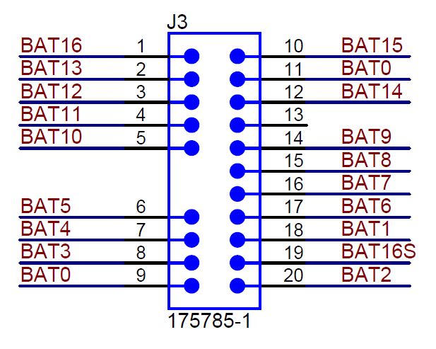
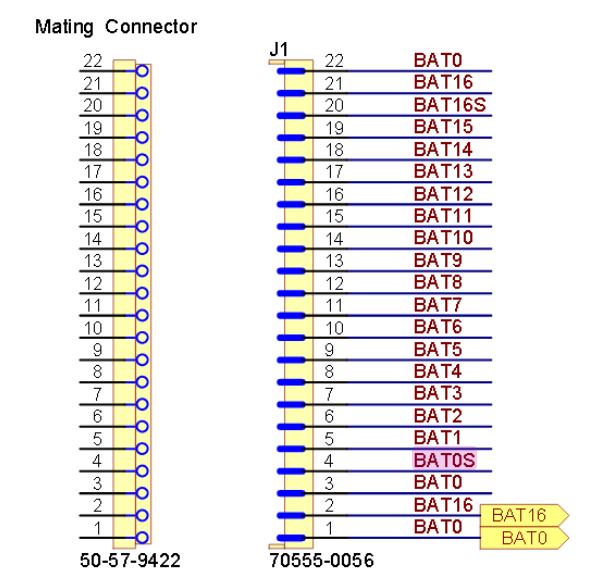
in the EM1402EVM, the two BAT0 (used for GND and negative reference for cell 1) are connected toghether. Why?

It is for not exceed the maximum ratings of VSENSE0 when you charge/discharge the cell connected?

Thanks
Regards

  • Hi Simone,

    Please be careful of the distinction between the BAT0 negative reference for cell 1 connected to local GND of the module vs. BATS0 connected to Vsense0 pin in the EM1402EVM schematic. In our design recommendations document for the bq76pl455a here: www.ti.com/.../slua791a.pdf section 5 explains the reasons for connecting Vsense0 in this way.

    Best Regards,

    Taylor
  • Hi Taylor, thank you for the answer.

    I know the difference between BAT0 and BATS0.

    But i see in the connector J3 2xBAT0 (same label) then i think they are connected togheter.

    The BATS0 is derived by BAT0 for VSENSE0 instead the bq76pl455a GND is connected directly to BAT0.

    Different is the connection of top of the stack:
    - 1 pin with label BAT16S that become BATS16 with resistor for VSENSE16
    - 1 pin with label BAT16 for the power of all circuits

    My question is, why there aren't BAT0S and BAT0 but the same label BAT0?

    In the other demoboard BQ76PL455EVM (below) there are two different pin for the connection to the cell1 (power and sense), BAT0 and BAT0S.

    Thank you
    Regards

    Simone

  • Hi Simone,

    Yes, you are correct BAT0 is tied together and there should be a separate path from the connector for BATS0 just as in the bq76pl455a EVM as this path prevents IR drop in the VSENSE0 path to gnd. This is best practice for any design.

    Regards,

    Taylor