Hello,
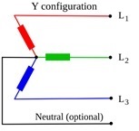
I need to design PFC with three phase input, Y connection (star connection: R, S, T, N - 4 wires) and one, common, 380V dc, non-isolated output.
Overall output power from 3 phases should be 9.9kW.
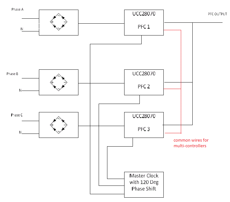
For equal power sharing between AC phases, I thought to use one UCC28070 based PFC on each phase (each input is between phase and neutral) and synchronize between 3 UCC28070 with an external clock source with 120 degrees phase shift and share between the 3 controllers the common signals according to multi controllers configuration connection according to figure 18 of the datasheet (identical to described topic in please, see an existing block diagrams in the linked topic, it describes my topology).
In my topology each UCC28070 based PFC should deliver 3.3kW, while this 3.3kW is equally shared between 2 interleaved phases of the UCC28070.
Operating requirement are as following:
Vin phase to return (effective voltage): 90Vac - 130Vac or 198Vac - 242Vac. It can be two separated designs, there is no need to support both input voltage ranges at the same design.
Output power from each UCC28070: 3.3kW (interleaving of 1.65kW par each switching phase of the UCC28070).
Overall efficiency: better than 98.5%.
EMI (conducted emission): per EN 55022, Class B.
The efficiency and conducted emission of the PFC are major goals, due to this fact I thought to build a bridge-less interleaved PFC.
According to SLUA517 there is a bridge-less design but there is no interleaving (the disadvantage is that the ripple cancellation is not available).
According to the following publication, which based on UCC28070, the interleaved bridge-less PFC is achievable ( https://delta-q.com/wp-content/uploads/2015/02/AHigh-PerformanceSingle-PhaseBridgelessInterleavedPFCConverterforPlug-inHybrid.pdf ).
Questions:
1. Do you think that the equal power sharing between 3 phases is achievable in suggested configuration?
2. Is it better to implement a bridge-less topology or semi-bridge-less topology (with to diodes for return path)?
2.1. May be semi-bridge-less topology is better from EMI point of view?
2.2. In a case of semi-bridge-less topology may be there is a need to bypass the diodes with MOSFETs. Does bypassing MOSFETscontrol can be generated from the synchronization clock and PFC MOSFETscontrol (kind of subtraction of the two signals)?
3. Do you think that EMI requirements can be met (this is the reason that I am interested in interleaving function, in addition to power stress sharing between interleaved stages) in suggested topology (I plan separate EMI filter for each phase, each UCC28070 PFC) ?
4. For testing the idea of current sharing I am planning to synchronize between 3 evaluation boards of 300W (UCC28070EVM), do you see any problem with this connection?
5. If the suggested idea isn't good, can you please suggest any other solution?
Thank you,
Alex.


