


Hey there,
We just wanted to run our project by you and ask a few questions :)
We are designing an AVR based device that uses the BQ24295 to charge lithium cells ranging from 4.2 - 4.35v, and 1400 - 10000mAh. The packs usually contain Gas Gauge IC's (such as the BQ275xx).
Assuming we understand the datasheet, this is how we plan to achieve this:
Note: OTG will always be pulled LOW. We will not be using Battery Boost Mode.
- CE is pulled HIGH by default from power-up, disabling Charging. (BATFET should be OFF, BAT should be 0V if no Battery is present) .
- Detect the presence of Battery (Check for Gas Gauge on HDQ bus > Check for Gas Gauge on I2C bus > Check Voltage at BAT with ADC > LOOP).
- If Gas Gauge is found, obtain Charging Voltage / Design Capacity / Taper Current.
- Set Charge Voltage Limit (REG04) using Charging Voltage from Gas Gauge, else Default to 4.208V.
- Set Fast Charge Current Limit (REG02) to 0.5C of Design Capacity, else Default to 512mA.
- Set Termination Current Limit (REG03) using Taper Current, else Default to 256mA.
- Pull CE LOW to begin the charging process.
The device will operate in one of two modes.
- Connected to a computer with a current limit of around 500mA, providing a continuous stream of data after a few seconds of startup delay.
- Connected to a USB Charger as a standalone device, with higher but appropriately limited charging current according to D+/D- detection.
At least, that's the plan. Heres our schematic:
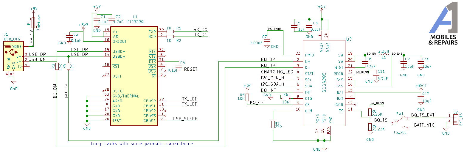
So now for our questions..
- Does our flow look correct? We can just leave CE HIGH, set the appropriate values in the register, and then pull it low to begin the charge cycle?
- Are we correct in assuming that with CE HIGH, BATFET is OFF, and BAT should be 0V? Should we also be be setting REG07[5] to 1?
- Is connecting D+/D- to another device (FT232R) going to cause issues with Charger Detection? If so, do you have any suggestions of a workaround?
- Is it acceptable to use resistors (R3/R4) in-line with D+/D- to reduce parasitic capacitance? Maybe lower values?The BQ24295 will be located much further from the USB port than the FT232R. We are hoping to avoid any unnecessary capacitance causing issues with USB Communication, not that there will be much.
- PMIDrequires a minimum capacitance of 20uF, but we couldn't find a maximum. Is 100uF too much?
- And finally, just a sanity check :) Do you have any suggestions? Does everything look/sound right?
Thanks in advance!
Bill
