This thread has been locked.

If you have a related question, please click the "Ask a related question" button in the top right corner. The newly created question will be automatically linked to this question.

DCR011205: DCR011205 5v output not present

Part Number: DCR011205

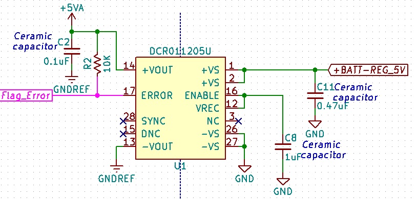
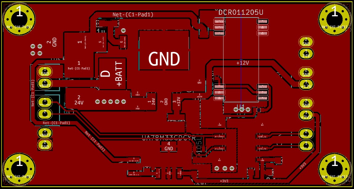
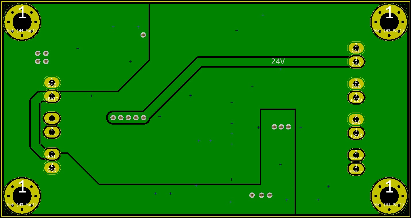
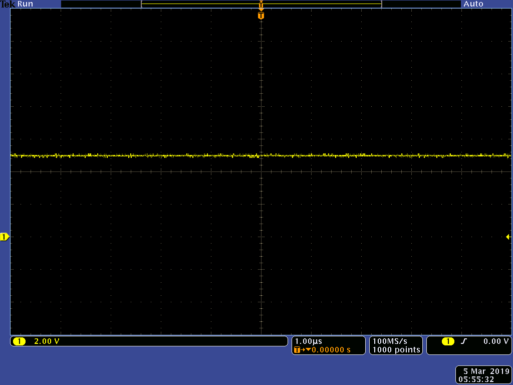
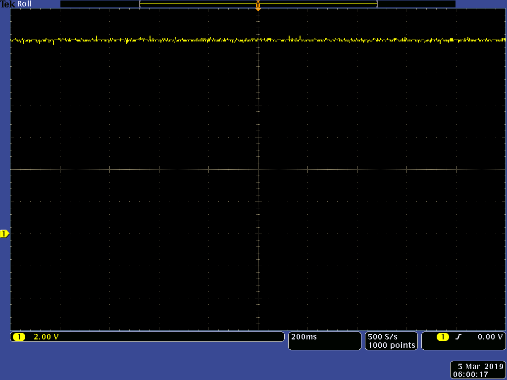
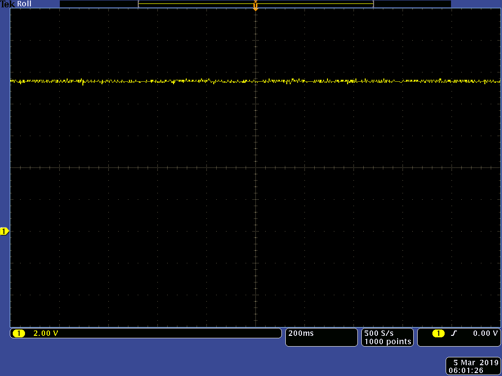
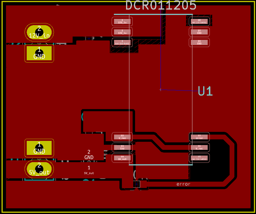
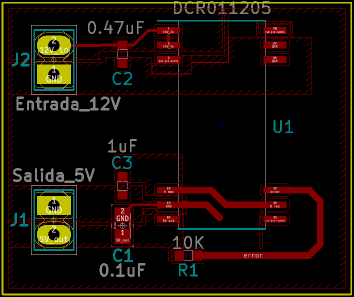
I am trying to generate an output 5V on DCR011205 for an ISO1050DUBR transceiver but it not present. On pin Vrec I see 7V and on pin (14) output a voltage of 0.6V approx. I supply 12V on both pins VS. Worth noting my GND and GND_ref on the electrical schematic they become the same on the bottom of PCB. I attached a PDF and image of the schematic I used. The configuration on the schematic is based on the datasheet of the device.

Best regards
Carlos Betancourt.MODULOlvc.pdf

  • Hi Carlos,

    Let me take a look at this and get back to you. If possible can you provide the PCB layout as well?

    Regards,

    Jimmy 

  • Hi Carlos,

    Connecting VS- and VOUT- should not impact the operation of the device. It should be regulated to the correct output voltage even with this connection.

    Can you probe the VS+,VOUT+, VREC and ENABLE pin and provide waveforms with an oscilloscope? This way I can get a better understanding of the behavior of your system.

    Regards,
    Jimmy
  • Yes, I can share my layout. Attached it like a PDF file. I have uploaded the top layer and bottom layer. I would like commented I did tests with an IC on protoboard and I had the same behavior. I am using ceramic capacitors. The board I made it by hand with a Phenolic plate.
    Best regards
    Carlos Betancourt.MODULOlvc-F.Cu.pdfMODULOlvc-F.Cu.pdf

  • Hi Carlos,

    Can you provide the waveforms that I mentioned in my previous reply? That waveform would help me understand what is happening to the device.

    Also can you confirm that the input and output capacitors are properly soldered on the board properly. I've had customers come back with issues that was resolved by swapping out a damaged output capacitor which would affect the stability of the DC/DC.

    Regards,
    Jimmy
  • Hi, Jimmy, I apologize for my late. I have many projects and recently I have time for this test. I would like to tell you, I made again the PCB but on breakout version. On this PCB I only test the IC DCR011205 and I have different results. I had a 5V on Vout pin for a few minutes but after my voltage fell to 2.6V. I repeated the test and my voltage on Vout now stay on 5V for a few secons. I attached the signals that you asked me. Also attache the new layout, the schematic is the same.

    The Vout pin when staying on 5V and his fell.

    This Enable pin.

    This +Vs pin.

    And Vrec pin

    It is worth noting that I have better results but they are not as expected.

    This the new layout.

    Best regards
    Carlos Betancourt

  • Hi Carlos,

    From your waveform it looks like it was able to regulate to 5V but eventually settled around 4V with what looks like output voltage noise spikes(roughly 1V) which seems rather high. Can you monitor ERROR_bar pin to see if the device is still within regulation throughout the test. Also what is your loading condition when you captured these waveforms?

    Your other waveforms show that VS+ is stable at 12V and that ENABLE and VREC voltages are identical which is expected. Do you have any silkscreen footprint that shows where the input and output capacitors are? I'd like to confirm that the input decoupling capacitor is as close as possible to the input pin to ensure low losses from stray inductance. 

    Another test that you can perhaps do is the following:

    • Increase input caps to from 0.47uF to 2.2uF and retest

    Regards,

    Jimmy

  • This is the layout with visible capacitors. 

    I am working on the waveform on the ERROR pin. 

  • I added two capacitors of 1uF on both +Vs pins and the regulator is working. I tested this configuration for approx one hour and Vout pin has 5V stable. I attached the new waveforms. It should be noted that the regulator has no load. I will test this configuration with load and share my results. All the before tests I made was without load. 

    Vout waveform

    +Vs pin

    Anable pin

    Vrec pin 

    Error pin

  • Hi Carlos,

    Depending on the length of your input leads from your power supply to the DCR module, the added inductance or if your input power supply is noisy, it will result in a higher input ripple. Having larger input caps will help with regulating this voltage. Please test this new schematic with different loading to confirm proper operation.

    Regards,
    Jimmy
  • I did many tests with a load of 125mA and regulator works fine.
  • Hi Carlos,

    Thank you for testing and reconfirming that the device is now operational for your application. I'll be closing this thread now that the problem has been resolved. Glad to help. 

    Please let me know if you need anything else.

    Regards,

    Jimmy