I have an LP5907MFX-3.3 deployed on a design and am experiencing odd behavior where the regulator turns slight on with an odd waveform, and after a period of time turns on fully, regardless of the voltage on the enable pin.
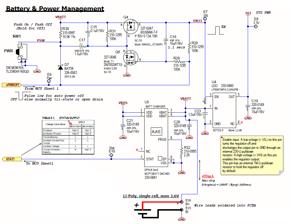
The power is supplied by a single cell LiPo battery, charged by an MCP73811 charge controller via USB. The regulator is connected directly to the Vbatt net due to the lack of power-path management. The enable line of the regulator is driven by a latching power circuit detailed here: mosaic-industries.com. A schematic snippet detailing the power circuitry is shown below:
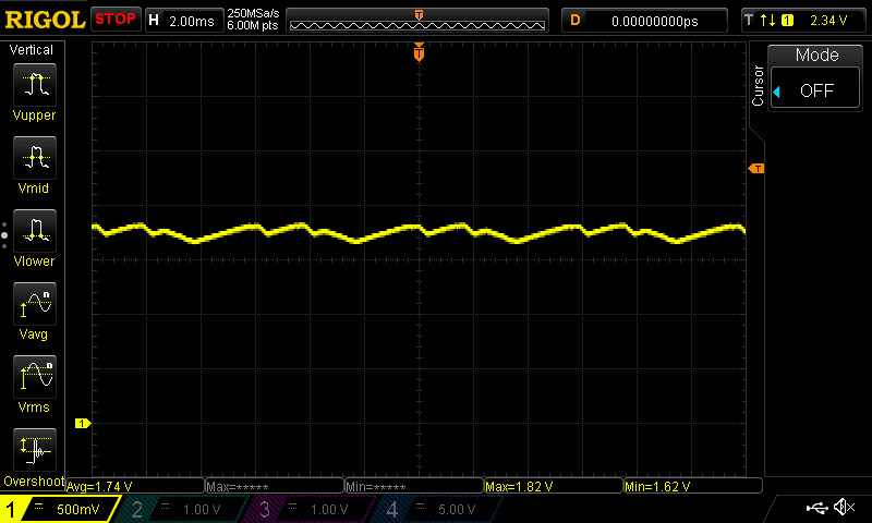
The rest of the system includes a microcontroller, bluetooth module, and I2C IMU. The odd behavior occurs after the battery charges fully, and results in a ~1.7V stepped waveform on the 3V3 net that results in brownout of the MCU. The enable pin is consistently held low at an average voltage of 140mV, and adding an additional 10kΩ pulldown (or even shorting to ground with a jumper wire) didn't change anything. A scope capture of the 3V3 net is shown below:
When the enable line is held low constantly what would cause the output to rise so high and fluctuate so much? Shouldn't the 230Ω internal discharge resistor on the output, activated when the enable line is low, prevent this kind of behavior?
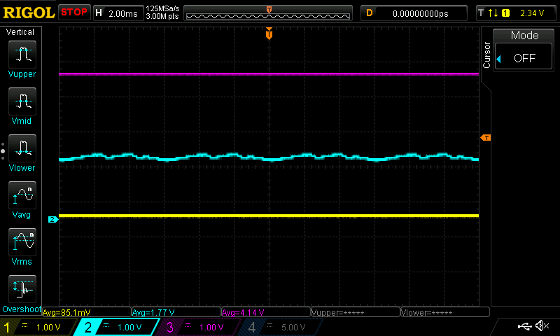
*EDIT* Additional scope captures follow below:
Another scope capture is below to show the three most relevant signals: Enable (yellow), Vbatt (fuschia), and 3V3 (cyan). Additionally, the nPWROFF signal has been physically disconnected from the MCU to ensure it's not influencing the circuit.
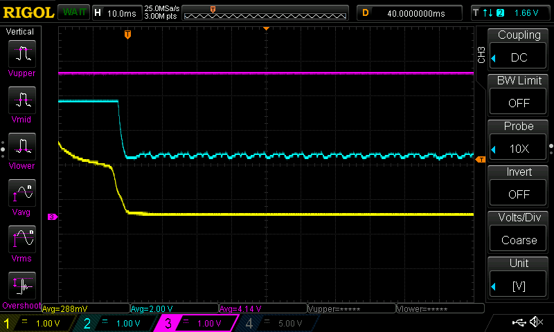
Another scope capture, this time showing the shutdown behavior when the power switch is held. Signals are Enable (yellow), Vbatt (fuschia), and 3V3 (cyan).


