This thread has been locked.
If you have a related question, please click the "Ask a related question" button in the top right corner. The newly created question will be automatically linked to this question.
Team,
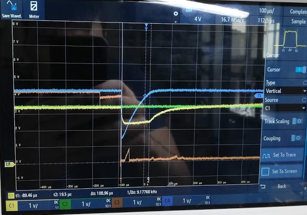
When LDO is enabled (from +3.3V) and experiences input voltage drop (from 4.3V to ~2V), it sometimes goes into instability and remains in it.
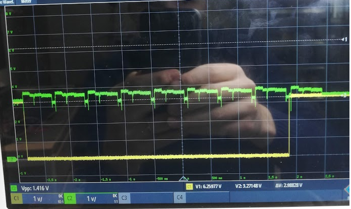
LDO then has still 3.3V (no load) on output when disabled and has ripple voltage up to 0-3.3V when load of 5-100mA is applied. When it's enabled, instability seems to exist for 400-500ms and then disappears. The drop from 4.3V->2V happens when circuitry that has a lot of capacitance is being turned on. Also in this mode, LDO cannot be turned off.
What we found was instability starts when LDO has more than 12uF of capacitance on the output.
Who can help us to resolve this (would share schematic and layout offline).
Thanks
TI Customer
Hi Ryan,
Ryan Eslinger said:From your description, you mention Vout is oscillating from 0 to 3.3 V when disabled. Is this the load or the LDO that is disabled? If the LDO is disabled, this implies that you have a leakage path onto the output from somewhere else in the application.
Our first thought was that this is leakage from other sources, but when we disconnect everything at LDO output, we can still see oscillation. From that we conclude, that this is LDO problem. This is LDO, that is disabled has some varying voltage on output and can not be disabled.
Ryan Eslinger said:The voltage drop on the input rail sounds like a load transient for your upstream supply caused by the inrush current of the circuitry with a lot of capacitance. Due to the drop in input voltage, the TLV702 will go into dropout and may even experience reverse current if Vout should exceed Vin during this time. Additional input capacitance local to the TLV702 should reduce the input supply's voltage droop.
*We have solved the drop problem by limiting capacitor inrush/charge current. This also helped with LDO oscillation, LDO is not going into that mode anymore, but we are afraid, that this might still happen in application, when external power supply is not stable (in old vehicles). So we also lowered output capacitance to 1uF (as oscillations appear at ~11uF). *
Ryan Eslinger said:In order for us to help debug, please provide a multichannel scopeshot showing Vin, Vout, Ven, and Iout. This will help us understand the relationship between the rails.
We can do such measurements, but i'm not sure how to measure output current. At attached picture is Vin (blue), Vout(yellow), InRushcurrent Enable(Orange) - (it's a bit spikey, because i was using a wire shorting it to ground) and LDO enable(green). After this moment LDO goes into oscillation and can not be disabled. Maybe this graph is enough? Output current can be measured, but we also saw this with no load at the output, so i doubt this would be of any assistance. After LDO is disabled, LDO still has voltage on output, but voltage is dependant upon load, we have seen higher voltages also, up to 3.7V.
Hi Ryan,
thank you for your feedback.
Green - Ldo output, Yellow - LDO enable pin.
Green ldo output, Yellow - LDO input voltage:
2. R1244 and R20 unpopulated:
Green - ldo output, Yellow - LDO enable signal. Ldo has 3.94V on output with no load, also when disabled. We have checked 2 devices.
Looking forward for your feedback.
Kind regards,
TI Customer