This thread has been locked.

If you have a related question, please click the "Ask a related question" button in the top right corner. The newly created question will be automatically linked to this question.

UCC28740: SIMPIS UCC28740 SIMULATION NOT WORKING

Part Number: UCC28740
Other Parts Discussed in Thread: TL431
Hello  ,
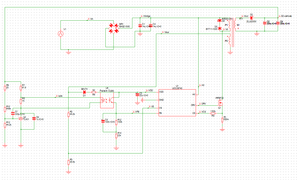
I'm designing a power supply using ucc28740 so I'm using the UCC28740_TRANS_SIMPLIS example circuit file of with 200V input and 5V @ 2A output. I'm facing an issue if I copy UCC28740 and paste in a new simplis schematic than I face the following error.

<<<<<<<< Error Message ID: 1023 >>>>>>>>

input file C:/Users/DELL/Desktop/SIMPLIS_Data/0.deck, line 63:

X$U1 22 0 25 29 26 24 11 UCC28740

Unable to locate the definition

of 'subcircuit UCC28740' in the

input, include, or library file(s).

On SIMetrix/SIMPLIS , Version : 8.20h

*** END SIMPLIS ERROR REPORT ***

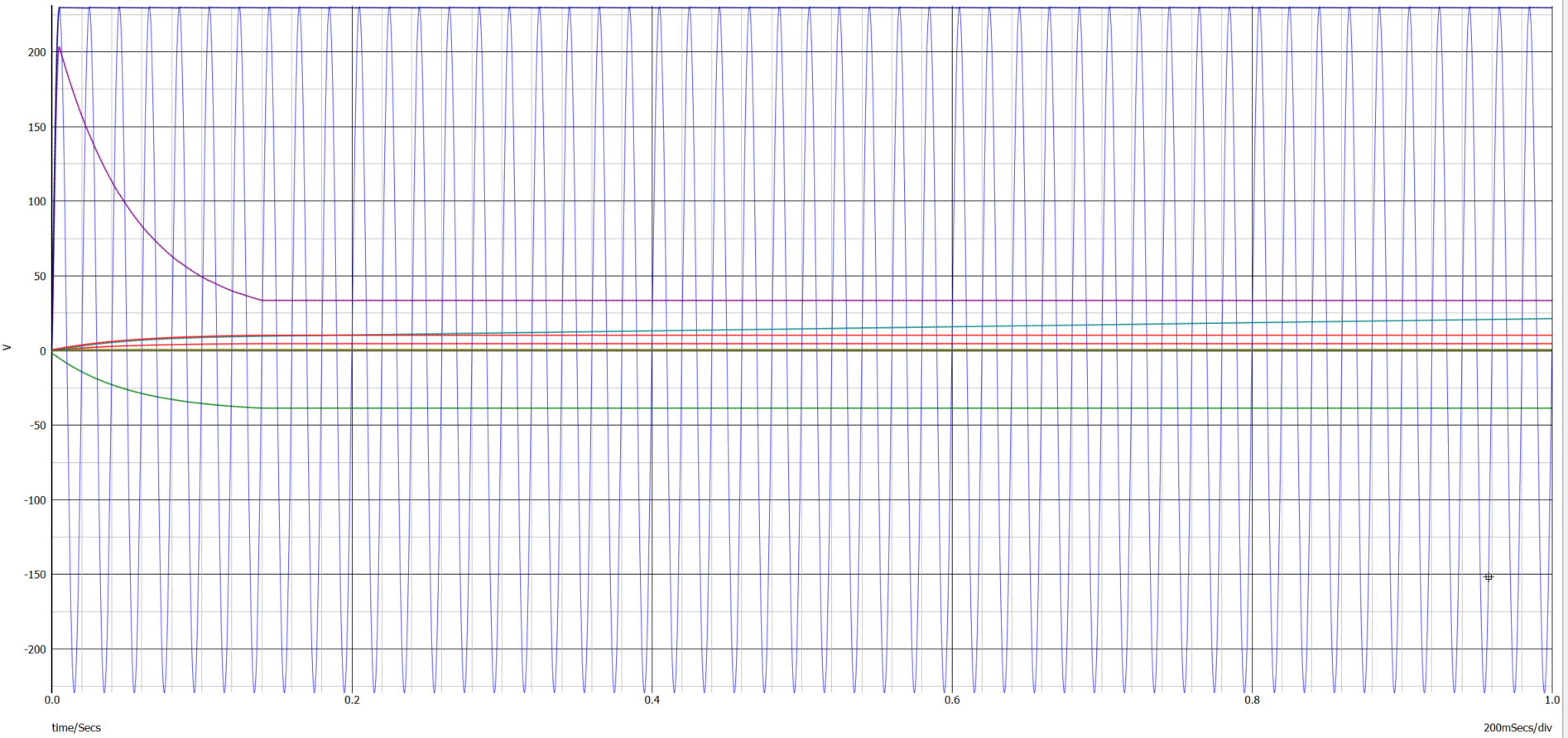
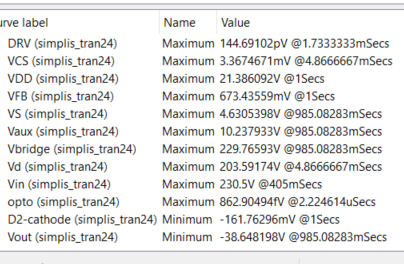
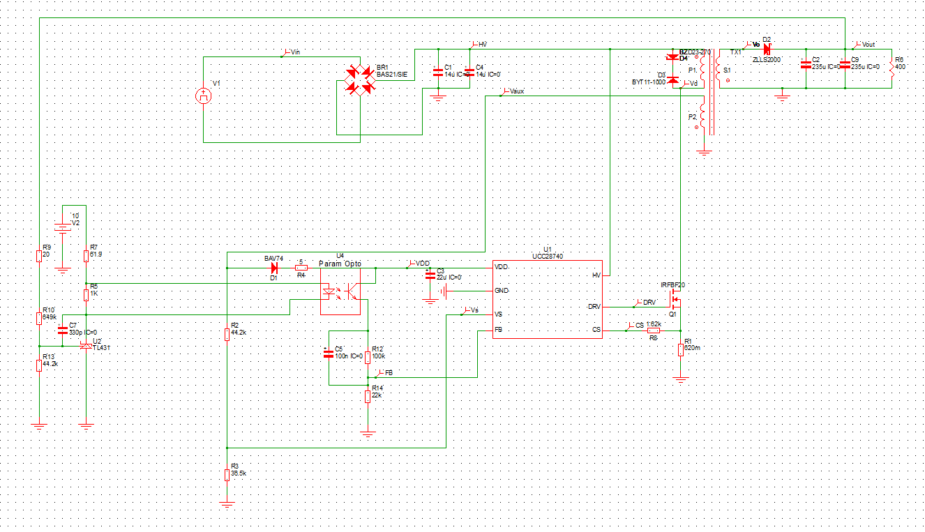
On the other hand if I edit the attached example circuit to use ucc28740 to design my own switch mode power supply to get 230V input and 40V @ 1.2 A output to design my required switch mode power supply than the circuit is not working. It is also mentioned in the example circuit of simplis that

1. The UCC28740 SIMPLIS Transient Model is encrypted and runs only in SIMPLIS versions 7.2d and above.

2. The testbench has been configured to show the Startup for VIN=200V,VOUT=5V , 10W, Iout of 2A

3. Please refer to datasheet for operating range.

4. All transients can be applied after the output voltage reaches steady-state.

so I just wanna know that the attached design example file test bench only work for this specific range of VIN= 200V , VOUT=5V,10W, Iout=2A or can I manipulate by using ucc28740 in a different design challenge ? If there is a specific range than how can I change the range of this test bench to design my power supply using UCC28740?
Thank you
  • Hello Hafiza,

    Thank you for your interest in the UCC28740 controller.

    I am not sure about your first error. I don’t know how to extract the subcircuit model of the UCC28740 alone out of the overall schematic file.

    However your second approach should work. I took the on-line transient file and modified it for 40V out at 1.2A. It took me several iterations, but I learned that you need to make sure the ALL of the components have been reconfigured for that new output requirement. It is not enough to simply change the line, load, transformer turns ratios and feedback divider.

    You must also change the UCC28740 VS input sense divider values (R16, R17), the current sense resistor (R1) value, maybe the line compensation resistor (R18), the TL431 compensation parts (R5, C12, C16), and others (Lm, etc).

    I recommend that you go through the UCC28740 Design Calculator tool
    (www.ti.com/.../getliterature.tsp )
    to find all of the parameters for your new design and modify everything in the SIMPLIS file to match those.

    You are, after all, changing a 10W design into a 48W design.
    I did not go through all of that, but I made enough changes (turns ratios, dividers, R1, etc) to be satisfied that the simulation does run to an equilibrium, but with some ripple because the feedback compensation is not optimized and maybe marginally stable.
    I think if you use the Calc tool values, you will have better results.

    Regards,
    Ulrich
  • Hello Ulrich ,
    I resolved my first issue .The model which goes along with the symbol for the UCC28740 is located in the original schematic - down in what we call the F11 window. so by pressing the F11 key to open the F11 window and scroll down to see the encrypted model. You can copy the model out of the F11 window and paste into a new schematic's F11 window and the converter would start working .
    I had that UCC28740 calculator and did all calculations from that but the design that is provided in the data sheet of UCC28740 and the BOM session of excel file I followed that and its a bit different from the simplis file that I found on texas instrument so I followed the excel file design but still the converter is not working correctly and I couldn't get my desired results.
    I have to apply 230V AC input rectify it and than passed it to the rest of the circuit but in the example simplis file they are giving PWL signal . I didn't use any PWL stuff in my circuit.
  • Hello ,

    Can you guide me how to resolve this error I'm facing this error while simulating my Switch mode power supply using UCC28740 flyback converter.
    <<<<<<<< Error Message ID: 5013 >>>>>>>>

    At t = 1.004878e+00, there is violation of KVL and/or KCL.
    Circuit is expected to satisfy

    0.0 = - 1.000000000000000e+00 V(X$U1.X$U1.C12) ( -3.027906143918431e+00 )
    + 9.990009990010198e-07 V(X$U1.X$U1.C5) ( 1.106716663665919e-07 )
    + -1.050958395789452e-05 V(C3) ( 2.145170762811143e+01 )
    + -2.014342383722836e-02 V(C4) ( 2.295539685056149e+02 )
    + 8.199780130431928e-03 V(C9) ( -1.634984740773678e-01 )
    + -9.681252930290217e-04 V(X$Q1.X1_BASE.X$CGS.C_SINGLE_SEGMENT) ( -2.201388813077066e-05 )
    + 9.999999999998402e-04 V(X$U1.X$U1.C11) ( 1.277668077537519e-05 )
    + 1.188868509547688e-02 I(X$U1.X$U6.I1) ( 2.000000000000000e-06 )
    + -4.042152931087810e-12 I(X$U1.X$U6.I2) ( 2.000000000000000e-06 )
    + 2.046666653844389e-09 V(X$U1.X$U6.VF1$TP_CCCS) ( 0.000000000000000e+00 )
    + 2.046666653844389e-09 V(X$U1.X$U6.VF2$TP_CCCS) ( 0.000000000000000e+00 )
    + -5.808577500822385e-16 V(X$U1.X$U6.X$U3.VF2$TP_CCCS) ( 0.000000000000000e+00 )
    + 9.990009990009991e-01 V(X$U1.X$U1.V15) ( 1.600000000000000e+00 )
    + -7.388194342116618e-04
    + 8.712866251233577e-05 V(X$U1.X$U6.X$U3.X$U4.A_OR) ( 5.000000000000000e+00 )


    The actual voltages/currents at this time instant
    are enclosed in parentheses.

    On SIMetrix/SIMPLIS , Version : 8.20h
    *** END SIMPLIS ERROR REPORT ***

  • Hello Hafiza,

    I'm sorry, but I am in "over my head" on this one. I barely know how to run Simplis and errors are too advanced for me.
    At this point, I will transfer your issue to the group that handles simulation issues.
    I'm sure one of them will be able to help you out.

    Regards,
    Ulrich
  • Hi Ultrich,

    Thank you so much that so nice of you will wait for the response.

    Regards,

    Hafiza Ramsha Mushtaq

  • Hi Ulrich ,

    Hope so you would be good and fine . I just wanna ask that had you contacted the simulation group regarding the error issue?

    Regards,

    Hafiza Ramsha Mushtaq

  • Hi Ulrich ,
    I'm sending you my file so I can get your help . When I increase time limit than I face the following error .
    <<<<<<<< Error Message ID: 5013 >>>>>>>>

    At t = 1.004878e+00, there is violation of KVL and/or KCL.
    Circuit is expected to satisfy

    0.0 = - 1.000000000000000e+00 V(X$U1.X$U1.C12) ( -3.027906143918431e+00 )
    + 9.990009990010198e-07 V(X$U1.X$U1.C5) ( 1.106716663665919e-07 )
    + -1.050958395789452e-05 V(C3) ( 2.145170762811143e+01 )
    + -2.014342383722836e-02 V(C4) ( 2.295539685056149e+02 )
    + 8.199780130431928e-03 V(C9) ( -1.634984740773678e-01 )
    + -9.681252930290217e-04 V(X$Q1.X1_BASE.X$CGS.C_SINGLE_SEGMENT) ( -2.201388813077066e-05 )
    + 9.999999999998402e-04 V(X$U1.X$U1.C11) ( 1.277668077537519e-05 )
    + 1.188868509547688e-02 I(X$U1.X$U6.I1) ( 2.000000000000000e-06 )
    + -4.042152931087810e-12 I(X$U1.X$U6.I2) ( 2.000000000000000e-06 )
    + 2.046666653844389e-09 V(X$U1.X$U6.VF1$TP_CCCS) ( 0.000000000000000e+00 )
    + 2.046666653844389e-09 V(X$U1.X$U6.VF2$TP_CCCS) ( 0.000000000000000e+00 )
    + -5.808577500822385e-16 V(X$U1.X$U6.X$U3.VF2$TP_CCCS) ( 0.000000000000000e+00 )
    + 9.990009990009991e-01 V(X$U1.X$U1.V15) ( 1.600000000000000e+00 )
    + -7.388194342116618e-04
    + 8.712866251233577e-05 V(X$U1.X$U6.X$U3.X$U4.A_OR) ( 5.000000000000000e+00 )


    The actual voltages/currents at this time instant
    are enclosed in parentheses.

    On SIMetrix/SIMPLIS , Version : 8.20h
    *** END SIMPLIS ERROR REPORT ***

    But when I decrease my time upto 1 second than it run but no voltages appear at the DRV pin
  • Hello Hafiza,

    I did contact the Simulation group and I received an internal indication that someone there is going to help you. Since I made the contact last Friday, it is possible that such help was delayed by the weekend.

    From your posting of the system-level model today, I do see 2 major errors and a few minor issues with your circuit:
    1. You cannot have the AC source grounded to the primary-side ground. This will short-out one of the diodes in the bridge and result in a short-circuit every other half-cycle. In a real system this would blow the protection fuse. In this simulation, you'll get half-wave rectification and huge current peaks out of the V1 source.
    => Please remove the GND symbol from the bottom of the V1 source.
    2. The polarity of the primary-Auxiliary winding is backwards.
    => Connect the dotted-end to GND and the non-dotted end to Vaux.
    3. Reconnect the VFB net to the top of R14, not at the top of R12.
    4. Disconnect the "soft-start" cap C8 from across the TL431. In real life it may help reduce output over-shoot, but in the simulation, it will just slow everything down too much just to get started.
    5. Your output voltage is ~40V. I think the TL431 model does not operate that high and may be clamping at start-up and conducting through the opto-coupler when the opto should be off. For simulation purposes, place a 10V source next to the TL431 and connect R7 to that source instead of to your Vout net. Keep R9 connected to Vout.
    6. 30ohms for R4 (in VDD circuit) may be a bit high. Please reduce the value of R4 to 5ohms for now, then change it later as needed to optimize after your system works.
    7. Consider to add some load to Vout, say 40V/0.1A = 400ohm resistor across the output.

    Hopefully with these changes you'll be able to get some switching signal out of the DRV output.
    I still can't help you with the error messages, but I'm hoping that the Sim-group will be in contact with you very soon.

    Regards,
    Ulrich
  • Hi Ulrich,
    First of all thank you so much for helping me out .I followed your instruction and did the required changes in the circuit than I get the attached file results.
  • Hi Hafiza,

    There is no file attached. Please try to attach and post again.
    Thanks,
    Ulrich
  • Hi Ulrich,

    First of all thank you so much for helping me out .I followed your instructions and did the required changes in the circuit than I get the attached file results.

  • Hi Hafiza,

    The latest run shows that the IC is attempting to switch at the ~1.5s point of the run, but some condition is out of spec so the controller goes into a UVLO-cycle shut down and tries to restart. You can see this by VDD rising to ~21V, you get a switching, then VDD decays down to ~8V and starts rising again. The IC is working as designed, but some circuit condition is not right for sustained operation.

    I am concerned that the drain voltage ta "Vd" is flat at ~35V even thought HV = ~230V. The D3-D4 clamp looks okay.
    Can you list the parameters that you are using for the transformer TX1, please?

    Regards,
    Ulrich
  • Hi Ulrich,
    In the above post I have both send you the simulation file (0160.Project.zip) and the design calculated values excel sheet (40V.xlsx)
  • Hi Ulrich,

    Looking forward for your response.

  • Hello Hafiza,

    I have some bad news, some good news and some more bad news:

    The bad news is that the modeling group kicked the problem back to me because they said the UCC28740 model was generated by a different group and they couldn’t debug it.

    The good news is that I was able to get a working simulation by using the system model provided on the TI website and modifying its parameters to match your circuit.

    At first, I took your model circuit (“Project.sxsch”) and tried to run it; first as received, then after making several changes. In both cases, I got the same non-convergence error that you did at ~1.5s into the sim.
    Since I can’t debug that, I decided to take TI’s model (“UCC28740_TRANS_SIMPLIS.sxsch”) and modify all of its components to match those values calculated by your “40V.xlsx” file.

    The result is a 15-ms simulation of start-up waveforms (which took ~10 minutes with a 2.3Ghz processor).

    Here are the changes that I made, plus some comments:
    1. The transformer in your model (in my sim environment) indicated 0 turns ratios and 189pH inductance, despite whatever numbers that you entered. There may be some compatibility issues with different revs of SIMPLIS.
    2. I took the TI-model transformer (xfmr) and redefined it for 900uH, P2 ratio 1:0.0522, S1 ratio 1:0.174, based on your turns P1 = 230T, P2=12T, S1=40T.
    3. Incidentally, these turn numbers appear to match the input voltage and expected output and Aux voltages of your system. This is not the way to define the turns.
    Also, the ratios of these turns do not match the turns ratios calculated and user-selected in the XL tool.
    The xfmr ratios are Nps= 5.75:1, Npa=19.167:1, but the XL tool shows 5.075:1 and 20:1 were chosen.
    In a simulation, the actual number of turns does not matter as long as the ratios are correct. For a real transformer design, now the number of turns becomes important. I recommend to set the model ratios to those of the XL tool.
    4. Your choice to start at 175Vac (XL tool cell C21) means that the controller will not allow start-up until it detects that the bulk voltage exceeds the peak value of 175Vac (which is 175Vac*1.414 = 247.5V).
    So your Vin source setting of 230Vpk sine wave would allow start-up anyway, even if there was no convergence problem. The sources are set with peak voltage, not rms. Also, you defined an offset so that all of the sine was above 0V (even though the peak was only 230V). You should define a 230Vrms AC source with 650Vpk-pk, centered at zero volts.
    5. I set the DC source in the TI-model at 260V, to get the system started. (I made it so it does NOT drop to 70V after 1ms.) For AC input, see #4.
    6. I changed most of the R and C component values to those of your XL tool. The ones not addressed by the tool, I left alone, since they were not important to getting the sim to work. Because of the Nps ratio of 5.75, the reflected voltage for 40V is 230V during flyback time, so I set the TVS to twice that =460V.
    7. I set the load current to 0.1A, and the output diode rating to 200V. (Note: the TI model uses piece-wise linear resistance models instead of actual diodes.)
    8. Since the xfmr Nps ratio is actually 5.75 but the XL-tool shows it as 5.075, this causes the lower VS divider resistor to be the wrong value, the output shuts down on an overvoltage at ~33V.
    Note: changing the Nps ratio will affect the recommended Npa ratio. When you change one, be sure to correct the other.
    To use Nps = 5.75 and Npa = 19.167, Rvs2 should be about 23K, not 36.5K.
    Otherwise, reset the xfmr ratio to the XL-recommended value of 5.075 and use Rvs2=31.6K (not 36.5K).

    The bottom line is to make sure all of the XL-tool values are correct (line by line) and that the user-selected values are close to the recommended values. The transfer these values to the TI-model and get that sim running. If you change any parameter, make sure to go through the rest of the entire XL-tool to adjust other parameters affected by that change. One change almost always affects something else, too.
    Once this is running correctly, then introduce your various component models (diodes, FET, etc.) one at a time and rerun the sim to verify that the model doesn’t cause a problem. If one of them does, then choose a different part or use a generic model that approximates the part you desire to use.

    It is less important that the actual components are used because the simulation will always be limited in what it can show you. It is more important that the overall system transient behavior is simulated, even with simplified component models.

    The final bad news is that I made one last Rvs2 value change and the simulation stopped working. It hangs up at a few microseconds and makes no progress. I can’t fix it, even if I go back to previous values. I did get several runs out of the model before it started doing this, so I think there may be a bug in the UCC28740 model that seems to count up to a certain number, then retains that number and hangs up. This will require debug from the group that made the model. I’ll find someone who can fix it, but I don’t know when that will be. (This could be weeks, not days or hours.)

    It may be possible to get around this problem by down-loading a fresh new (“UCC28740_TRANS_SIMPLIS.sxsch”) model from our website and rename it as a master copy of this model. (Move your old one to a separate folder.) Then make a copy of the new one and make most of the circuit changes that I described above, and then save that as a modified master. Then run simulations on copies of the modified master, making various changes until it stops working. Then transfer the latest changers to a new modified copy and run sims from that until it too hangs up. I know that is tedious, but I don’t have any better idea until the model gets fixed and runs all the time.

    Regards,
    Ulrich
  • Hi Ulrich,

    Hope so you would be good and fine . The changes you have recommended me I tried them before, the problem is that  my input is AC of 230V with minimum of  180V and maximum of 295V while in the example circuit provided by texas instrument they have used PWL sources and resistors but I can't do so because my input requirement don't support PWL source due to which I couldn't use PWL resistor as well .I'm using UCC28740 excel sheet calculator and they didn't give me that much  calculation information regarding the optocoupler ,PWL resistor used in the model (“UCC28740_TRANS_SIMPLIS.sxsch”) .I also don't know how they calculated the different values for PWL resistors.