This thread has been locked.

If you have a related question, please click the "Ask a related question" button in the top right corner. The newly created question will be automatically linked to this question.

CSD97394Q4M: Used as BLDC.

Part Number: CSD97394Q4M

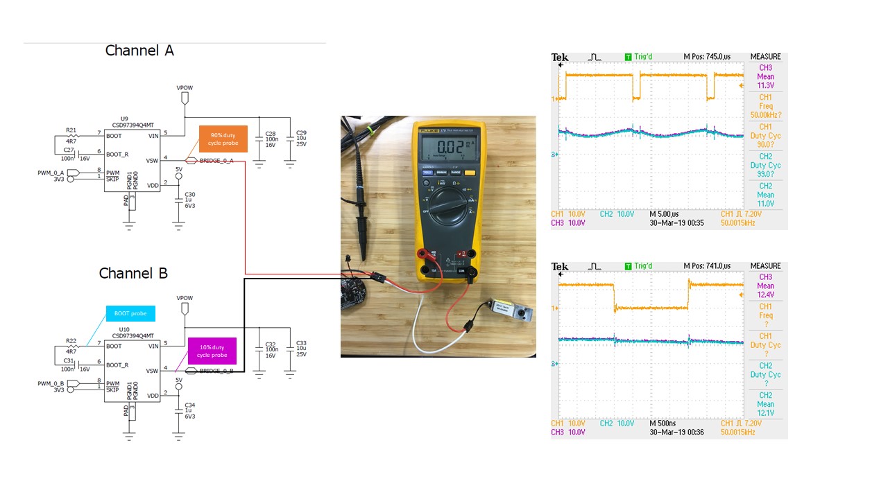
In our implementation for the CSD97394Q4MT as BLDC driver we are observing that the channel with lower PWM duty cycle is not able to pull the voltage low. Please see schematic below:

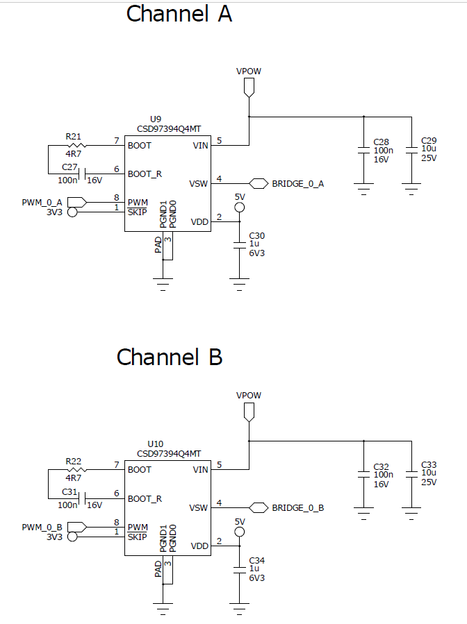
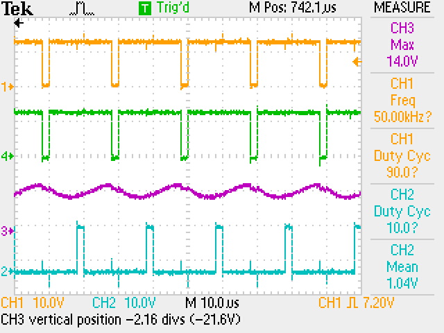
We are connecting one lead of a solenoid to BRIDGE_0_A and the other lead to BRIDGE_0_B, the solenoid is rated for 12V (68 Ohm resistance). We are injecting two PWM (50 Khz)) signals to Pin 8 on each channel. The duty cycle for CHANNEL A is 90% and 10% for CHANNEL B, image bellow shows the output in VSW pin (BRIDGE_0_A and BRIDGE_0_B). Orange and Cyan signals are what we measure from the VSW pins (BRIDGE_0_A and BRIDGE_0_B) when the bridge signal is not connected to the solenoid, and the Green and Purple signals are the output we are measuring (with oscilloscope) when the solenoid leads are connected to BRIDGE_0_A and BRIDGE_0_B (VSW pins for each CHANNEL). For some reason the channel with lower duty cycle is not able to pull the signal low sometimes, and we will observe the same result if we invert the duty cycle for the channels.

Any idea of what could be happening is appreciated.

Thank you for your time.

  • Jose,

    CSD97394Q4 was NOT designed for Motor Control or Solenoid drive applications. It was strictly intended for Multiphase computing applications with Power Saving modes.If the duty cycle is too narrow, meaning the inductor current is too low, the internal Current detector circuit might be Zero-cross tripping and self-clamping Low side FET drive.

    To clarify this, please use a Current probe and show us the inductor Current.

    Second probe I need you to display BOOT pin voltage on top of Switch node voltage for the Power Stage leg creating you the above issues.

    Third prove I need you to zoom in on input PWM signal since CSD97394 has tri-state level detection.

    Best regards.

    Lucian

  • Thank you for the feedback Lucian,

    I also want to point out the we are using the CCM mode by setting the #SKIP pin high, disabling the diode emulation. By disabling the diode emulation and according to the functional diagram in the datasheet this would behave as an H-Bridge.

    Regarding the internal current detector, what is been used as current detector in the Functional block diagram for the part in page 6?

    There is also a thread where one of my coworkers asked about using this part as BLDC before implementing it in the design (Use CSD97394Q4M for BLDC control?)

    See suggested measurements below; I do not have a current probe but I used the Multimeter in line.

    Thank you for your time,

    Jose

  • Jose,
    By connecting SKIP pin high, the internal Diode Emulation mode should be disabled. The part should operate in CCM mode, like a Half-bridge.
    Can you please capture some waveform showing the moment CSD97394Q4M is misbehaving? When the Switch-node is not collapsing to GND, is there positive or negative inductor current?

    Best regards,
    Lucian
  • Lucian,

    My previous post was showing the CSD97394Q4M misbehaving, see the Cyan/purple (Channel 2 probe) signal, and the current draw in this case is ~0 because there is not voltage difference between Channel A and B. In my initial post, GREEN and CYAN signals show the moment the CSD97394Q4M is working as expected, the current draw should be 176mA.

    I also wanted to point out that if we observe this issue, most of the times we could fixed by power cycling the CSD97394Q4M chip, but if we left the system disconnected overnight we will observe the issue during the first boot the following day; I could also reproduce it by discharging all the CAPS associated with CSD97494Q4M part manually, which indicates to me that the issue is related to a capacitor charging time, maybe the Bootstrap circuit?, or the internal hysteresis comparator connected to BOOT_R pin?

    Thank you again for your time and attention,

    Jose
  • Jose,

    Your issue is related to the Boot Cap charging requirements before you begin switching the Power Stage. Your H-bridge circuit is essentially different from a Synchronous Buck converter for which CSD97394Q4M was intended to be used. Before your first PWM pulse comes in, Boot Cap needs to be charged with min 4V across it to satisfy the UVLO threshold and allow the HS driver to fire the first pulses. There's an internal 40V HVPMOS between 5V rail to BOOT pin. Also, switch-node must start from a low impedance level wrt GND to allow Boot Cap to charge. In Buck converter, Vout Caps are an order of magnitude larger than Boot cap and Vout always start low or at a pre-biased DC level. As such, Boot Cap gets correctly pre-charged before each start-up. In your case, Boot Cap needs to charge through your 68ohm solenoid DCR and through the switch-node of the opposite Power Stage which might be tri-stated in Hi-Z impedance state. That's why sometimes you can start , sometimes you don't. If you managed to get it started after the first few pulses, then Boot cap will re-charge on a pulse-by-pulse basis when LS FET is turned ON.
    The opposite Power Stage has switch node in Hi-Z (both HS and LS FETs are in OFF condition) if you don't actively drive it.
    That's why your application starts working normally after you manually reset all the caps , including BOOT caps and switch-nodes.
    It seems Bootstrap operation with both HS and LS UVLO levels might not be optimum for your application. A circuit with a driven charge pump switching independently of Power Stages and properly charging both floating Boot Caps might guarantee a clean start each time.
    That's why I asked you to use a Differential probe and capture the floating voltage across Boot Cap before you start PWM drive. If Boot voltage dips below 4V , you're likely going to lose HS drive and Skip pulses.

    Best regards.
    Lucian
  • Thank you for the details Lucian,

    Based on your comments, I have modified the PWM signal to start low for few milliseconds at boot for both Channels A/B; letting the Boot Cap to charge through the solenoid; that seems to have fixed the issue I was having, and also explain why the channel with the lower duty cycle was presenting the issue.

    Thank you again for your great feedback.

    Jose