This thread has been locked.

If you have a related question, please click the "Ask a related question" button in the top right corner. The newly created question will be automatically linked to this question.

TLV62130: PG pin is always high

Part Number: TLV62130
Other Parts Discussed in Thread: TPS62133, ,

Hi,

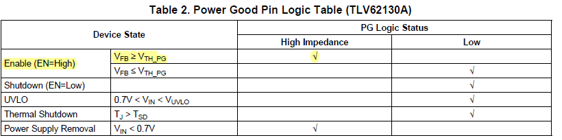
I'm experiencing a problem with PG pin of the TLV62130. As per manual: 'With TLV62130 it is high impedance when the device is turned off due to EN, UVLO or thermal shutdown.' In my design it's pulled up via 100kOhm resistor to the output of TLV62130 but in my case PG is always staying high, even when IC is working normally and not shut down by EN pin or under UVLO/thermal shutdown. TPS62133, when put onto the same board, controls PG pin without any issues, it's pulling it low during normal operation. My design is just a generic one based on TLV6213x EVM module and part's datasheet. Thanks!

  • Hi Yury,

    Please clarify if my understanding is correct. With TLV62130_130A, PG pin goes HIGH impedance when Vout is within regulation (working normally) which is correct as stated in the table below. You can refer as well to EVM user guide (http://www.ti.com/lit/ug/slau416a/slau416a.pdf) for reference waveforms (Fig. 15 & 16).

    For the correct logic level of PG pin at different device state, you need to check the device marking to determine if it is 130 or 130A as indicated below.

        - TLV62130A: VUNI

        - TLV62130: VUBI

    Best regards,

    Excel

  • Hi Excel,

    Thanks a lot for your answer, I definitely have a TLV62130 version, not the 'A' one.

    Do I understand correctly that PG pin won't stay low during normal operation? According to the link you provided it won't, actually, I see similar behaviour, when power is applied - PG is blinking once and then stays in high-z state.

    Datasheet is a bit confusing, it says following: 'The TLV62130 has a built in power good (PG) function to indicate whether the output voltage has reached its appropriate level or not. The PG signal can be used for startup sequencing of multiple rails. The PG pin is an open-drain output that requires a pull-up resistor (to any voltage below 7 V). It can sink 2 mA of current and maintain its specified logic low level. With TLV62130 it is high impedance when the device is turned off due to EN, UVLO or thermal shutdown.'

    So it should be indicating whether the output voltage has reached it's appropriate level or not, so I assume - it should somehow stay in low state to indicate that? 'and maintain its specified logic low level' - isn't that a correct behaviour? TPS62133 is doing that, here's my schematic and I can see PG goes to almost zero during normal operation and goes high-z on thermal shutdown, for example.

    As far as I understand, Vth_pg is 95% of Vfb which is, in turn, 800mV. So yes, you're correct and device would be in High-Z mode, but what PG pin is used for then? It's indicating 'POWER_GOOD' only during short transition from zero to 95% of 0.8V and then goes High-Z again...

    Thanks a lot for your help!

    Best regards,

    Yury.

    P.S. Please note that I've changed R2 to be 680k and R3 to be 130k so don't worry about these.

  • Also, I've found one more mistake in my design - C3 should be connected to AGND, that's already fixed.

    And one final question - in WEBENCH it says that R3 shouldn't be over 180kOhm, while in datasheet it says 'The voltage at the FB pin is regulated to 800 mV. The value of the output voltage is
    set by the selection of the resistive divider from Equation 6. It is recommended to choose resistor values which
    allow a current of at least 2 uA, meaning the value of R2 should not exceed 400 kΩ'

    Which one would be correct - to use no more than 180kOhm or no more than 400kOhm? Thanks!
  • Hello Yury,

    Just to summarize the issues you highlighted.

    1. PG function

    Answer: PG stays high impedance when Vout is greater than or equal to 0.95*Vout and goes to low impedance once Vout dropped to 0.90*Vout. See below figure.

    If your target is to turn-on the LED once PG goes high impedance (Vout > 0.95*Vout) and turn-off (LED) when PG goes low impedance (Vout < 0.90*Vout) then I proposed a different circuit (see schematic below). It seems there is a problem with the original schematic because once Vout is equal or greater than 0.95*Vout (PG = high impedance) then LED will turn-off because the gate and source pins of the FET are at equal voltages. Because it is a PMOS, it requires that the gate pin is negative voltage with respect to the source pin to turn-on the FET. If that it the case then the LED will only turn-on when the PG is low impedance which is when Vout < or equal to 0.90*Vout. (Note: Replace D1 with your LED and Q1 (NMOS) with higher current capability).

    2. Vth_PG level

    Answer: The Vth_PG is sensing Vout using a resistor divider hence it is not limited to 800mV. Refer to the waveform above which was taken in the EVM User's Guide document (SLVU437A) where PG goes high only Vout = 3.3V

    3. FB resistor divider criteria

    Answer: Both 400K or 130K are both fine but it is best to use 130K on R3 in your schematic to ensure that FB pin will not be influence by external noise.

    Best regards,

    Excel

  • Hi Excel,

    Thank you very much for your answers! In regards to PG pin, according to your proposed schematic during thermal or UVLO shutdown LED would stay off only because TLV62130 would shut down its output, is that correct? I used PMOS intentionally as according to datasheet it looked like IC would be sinking current by enabling integrated N-MOSFET when the output voltage is within nominal values (>95% of Vout) and would keep that N-MOSFET on all the time while voltage is within that limits. Now I understand that it's actually an opposite behaviour - IC keeps PG low only when VFB ≤ VTH_PG. But if I'm correct this means that PG can't be connected to any external power rail to indicate power good as during thermal shutdown PG pin would stay in High-Z. Anyway, thanks for your clarification, I really appreciate your help!

  • Hi Yury,

    LED will stay off if thermal or UVLO shutdown occurs. With the proposed circuit even though PG is high impedance, there will be no supply (Vou is disabled) on LED to turn it on and in the same way with the original circuit (only difference is in original circuit it will turn-on temporarily until Vout is not enough to supply the LED).

    If you want to have a PG = L during Shutdown, UVLO and Thermal shutdown, you can choose TLV62130A. This will satisfy your requirement with external bias on PG. See fig. below.

    Best regards,

    Excel

  • Thanks for your help, Excel! I'll redesign my board to comply with your suggestions!
  • Hi Yury,

    Great.
    I will close this thread for now.
    Feel free to send your query if encounter any issue again.


    Best regards,
    Excel