This thread has been locked.
If you have a related question, please click the "Ask a related question" button in the top right corner. The newly created question will be automatically linked to this question.
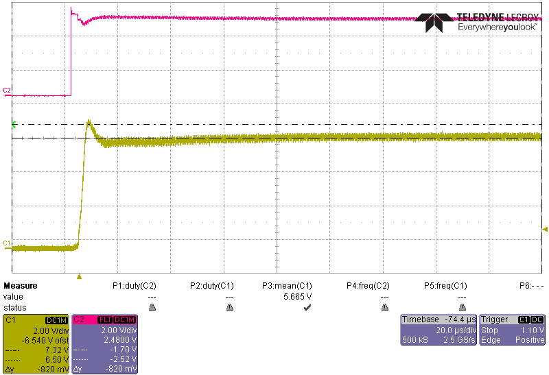
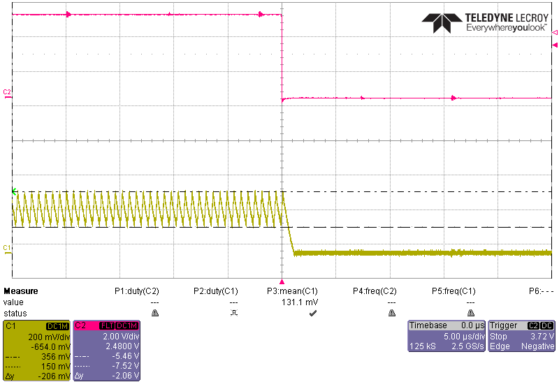
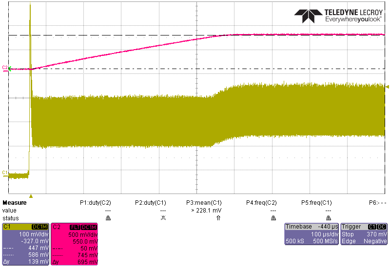
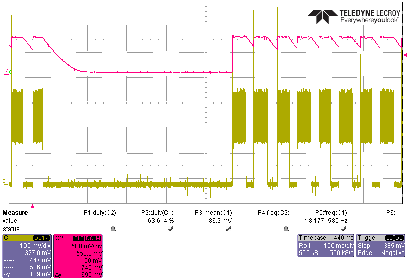
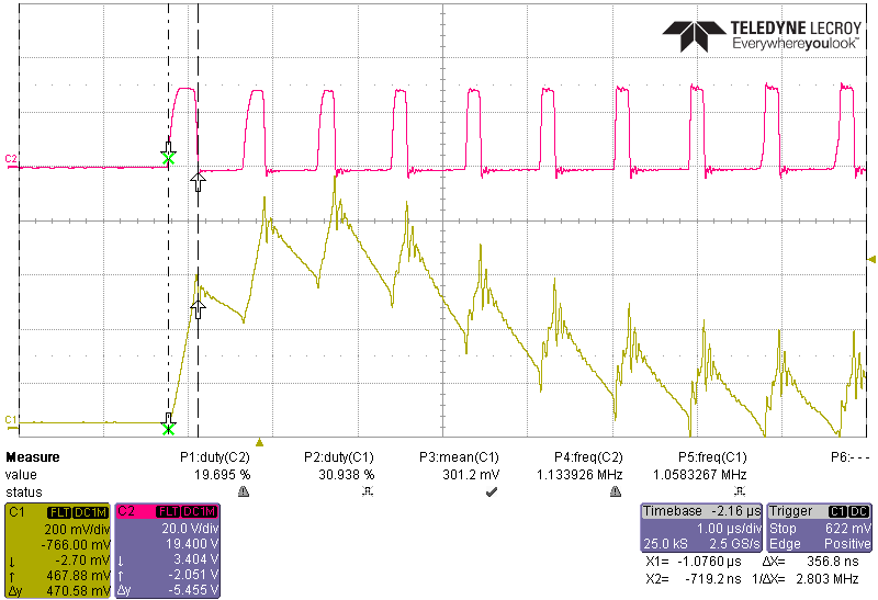
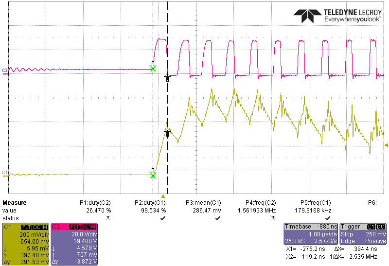
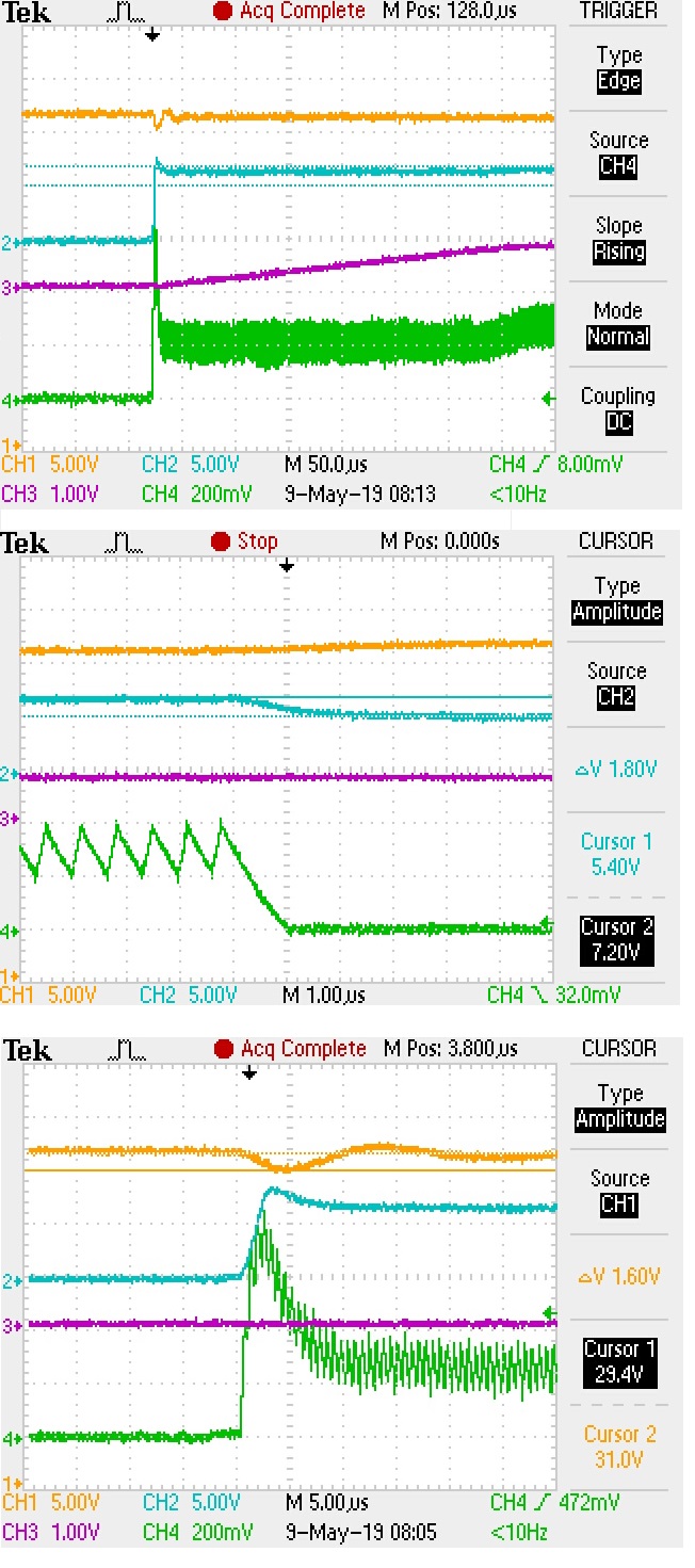
I am noticing a significant spike when ever PWM pin is enabled from the disabled state as shown below in figure 1 at upper input voltages around 30vdc. Web bench does not show this anomaly when simulating PWM however the PWM is much faster in the simulation. Web bench does show a similar spike in simulation ( figure 6) for the startup conditions which occurs while the comp capacitor charges but this spike is much smaller in than I measure in the simulation. If I calculate the value of Ipeak which can occur at start up I get 2.8A @ 30v, which is also lower than I am measuring in figure 2. As seen in figure 1 Vcomp is dis-charged so this would make sense that the system is going into minimum pulse width mode. Note the on time during the spike is larger than the on time in normal operation in figure 3 & figure 4. I would have expected it to be = Ton min 140nS. It seems to be worse when Vcomp only partially discharges than when it fully discharges. Any thoughts on why that may be or how to resolve the issue?
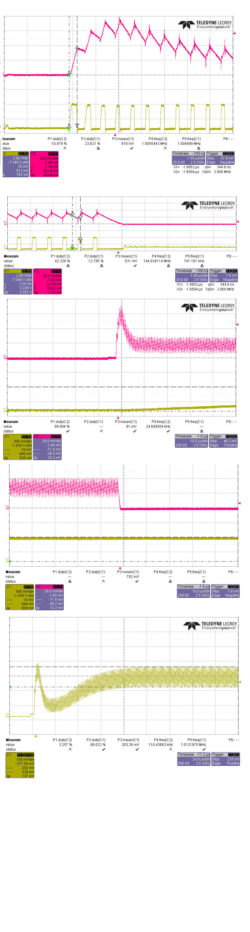
Figure 1: Yellow: Short Current spike measured across a 0.2 ohm resistor. Pink: Vcomp pin
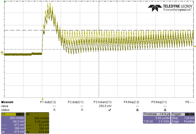
Figure 2: Zoom Short Current spike measured across a 0.2 ohm resistor. On time 228ns
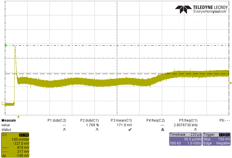
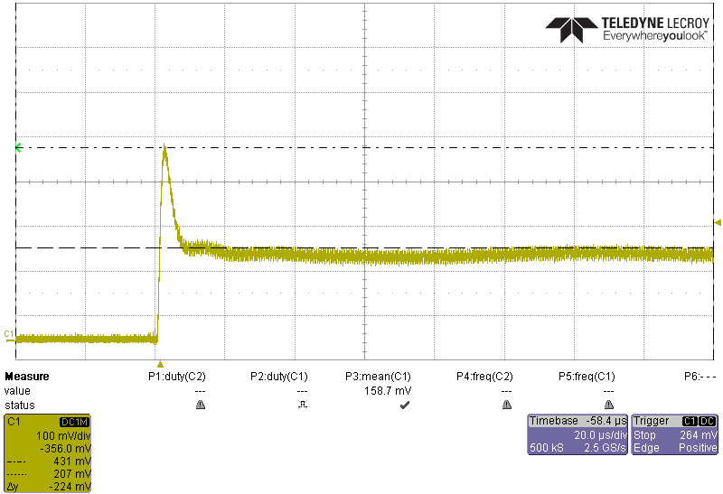
Figure 3: measured across a 0.2 ohm resistor standard current profile. On time 183ns
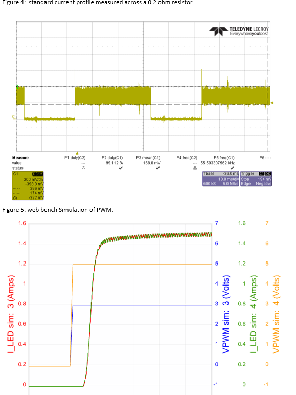
Figure 4: standard current profile measured across a 0.2 ohm resistor
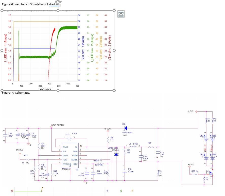
Figure 5: web bench Simulation of PWM.
Figure 6: web bench Simulation of start up.
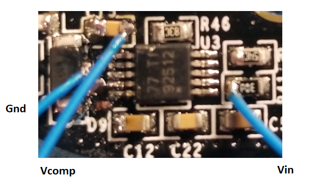
Figure 7: Schematic.
Above: yellow V out, Pink: pin 4 Pdim
Below: Yellow I out at off transition, Pink:4 Pdim
Below: Yellow: I out, Pink pin 8 Vcomp
Below: Yellow: I out, Pink pin 8 Vcomp Zoomed out
Q1: There are actually 3 transistors/LED paths that are enabled one at a time to select different colors. During my testing only one path is enabled so I am only showing that to simplify the discussion.
Note: I shorted out the transistor today and saw no difference.
FB4: this is a ferrite bead max 0.15 ohms at DC.
Note: I shorted out the Ferrite bead today and saw no difference in the spike.
Below : i put a 1uF cap on Ccomp you can see this stabilizes Vcomp but the current spike is still there. I also tried going to a smaller cap but it did not change much.
Below: R46 IS CHANGED TO 100K too reduce thew switching frequency. the resulting spike increases slightly.
One more image below: Pink is the output from pin 10 to the inductor. Yellow: is the current spike. the first 3 pulses are too large then it stabilizes.
Below you can see light yellow with standard Ccomp 10nF. Dark yellow is with Ccomp set to 1uF. the spike goes up a bit but duration is about the same.
Changing C13 to 11uF there is only a 1.86A spike on the LEDs. However the inrush spike over all in the system increases to 6 amps due to the increased current to charge C13. I would need to increase my current sense resistor power, it's also a larger EMI spike.
Changing C13 to 2.2uF brings spike on the LEDs to 3.15A. The inrush spike over all in the system increases to 4.26 amps due to the increased current to charge C13.
Below Current through 1/3rd of the leds across a 0.41 ohm resistor with C13 = 2.2uF
Hello James,
I'm not understanding why it's doing this. Can you look at Vin, Vout, the current spike and COMP (comp will need to be zoomed in to see if it's moving after the PWM goes low, right when the PWM goes high and during the recovery as seen above in the current. The Vin I'd like to see is right at the power stage near pin 2 of the IC with the probe return near the IC as well near pin 9.
Being the response doesn't look a lot different between the 10n and the 1u during the overshoot it seems as though another variable is causing this.
It would be good to see what the duty cycle is at the end of the PWM pulse before it turns back on also including Vin, Vout and current.
Best Regards,
The LEDs are on the same 4 layer PCB as the converter. The furthest LED is 3.4” from the center of the converter IC.
Critical probe location view.
i used a 4 channel scope to get all the readings at once. the results are not as clear so if you want a zoom of something let me know.
On all grabs,
Channel 1: Vin
Channel 2: Vout
Channel 3: Vcomp
Channel 4: I out
Images are in the order: Pwm on until current V comp stabilizes.
Zoom: PWM turning off
Zoom pwm turning on.
It could be too high of a frequency but it’s what the TI Simulation tool recommended, at 32v it’s right around the minimum on time but even at 28v where there is more wiggle room the spike is still there. If I use a 10uH inductor and set the frequency down to 1 Mhz the spike is right around the same height as the standard current wave which unless i am missing somthign else seems to solve the issue. I will have to find a way to fit that bigger inductor.
Images below in order
1. Pink Current, yellow Switch node. ( PWM low to high) Note the extended on time on the first few cycles.
2. Pink Current, yellow Switch node. ( PWM high to low )
3. Pink Current, yellow Vcomp. ( PWM low to high)
4. Pink Current, yellow Vcomp. ( PWM high to low )
5. Current with a 10uH inductor 1mhz Operating frequency.
The current in my last email is the current sense resistor current which would include the capacitor current. However previous screen shots like the one below have shown the current through the LED's has a similar current spike. I think we have a solution now of increasing the inductance and decreasing the frequency, I will have to find some parts that will fit and then run it on a larger sample set. Thanks for all your help.
Below is the current spike which occurs though the LEDs with Fosc = 1.4Khz, Inductor =4.7uH. the current shown is 1 of 3 parallel paths of LEDs across a 0.41 ohm resistor.