This thread has been locked.

If you have a related question, please click the "Ask a related question" button in the top right corner. The newly created question will be automatically linked to this question.

UCC28070A: Synthesized Questions of UCC28070A (continued)

Part Number: UCC28070A

Hi John,

1,

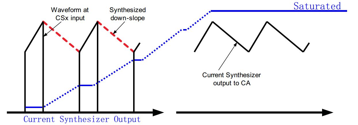
So,during inrush surge events at power up and AC drop-out recovery, VVSENSE < VVINAC, the synthesized downslope becomes zero like the blue curve I drawn below?

2, During normal operation, off-time down-slope emulation is decided by the formula below.

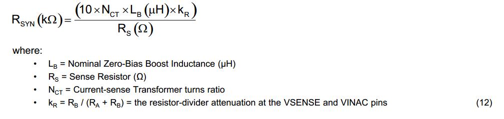
But, how could you ensure that the down-slope emulation is accurate while the L value would change with the current flowing through it??? I mean,  L changes, down-slope changes, but the formula above didn't take the inductance variation into consideration.

  • Hello Jankel,
    Yes your blue drawing on the right hand side shows the down slope as zero.
    That is correct.
    The equation 12 above is only an approximation for the inductor current.
    During the switch off time the current in the FETs is zero and so you make the assumption that the current decays linearly from the peak sensed value of CSA (just before the switch turns off) to the peak sensed value of CSA (just when the switch turns on).
    But because the FET current is zero you use the no load value of inductance in the calculation for the RSYNTH resistor.
    As you say the inductance will change with current but it should not change a lot.
    Hope this answers your question
    Regards
    John
  • Hi John,

    One mistake in your reply above:

    The current decays linearly from the peak sensed value of CSA (just before the switch turns off) to the peak valley sensed value of CSA (just when the switch turns on).

    But if the off-time current assumption is made like this, how could it flatten out at the saturated voltage value during inrush surge events at power up and AC drop-out recovery?? If the off-time emulated current always decays from the peak sensed value of CSA to the valley sensed value of CSA. There must be emulated rising current during off-time, right? But if like what you said, how could it rise?

    My guess is, once VVSENSE < VVINAC, the off-time emulated current would rise through charging the internal capacitor until saturated rather than decaying from the peak sensed value of CSA to the valley sensed value of CSA.

  • Hello Jankel,
    The data sheet is saying that the pwm is zero when VINAC is greater than VSENSE.
    Thats all it means.
    I think the data sheet could be written better to describe this and it is a little bit confusing.
    PWM is held off until VINAC is less than VSENSE
    During an inrush condition this protects the FETs.

    Regards
    John