This thread has been locked.

If you have a related question, please click the "Ask a related question" button in the top right corner. The newly created question will be automatically linked to this question.

TPS4H000-Q1: Load current

Part Number: TPS4H000-Q1

Hi team,

My customer is evaluating the TPS4H000-Q1.  Could you support the following questions?

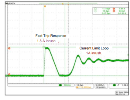
1. The d/s states that the recommended nominal DC load current is 0.75A(max).  Is it acceptable to satisfy 0.75 A with average current or RSM current(not DC)?  If it's ok, how much current does the device can handle?  I believe that the device can handle the current within the limits of current limit(ICL) and TSD.

2. Could you let me know the current limit response time? Is it 1us(typ)?

Regards,

Yamaguchi

  • Yamaguchi-san,

    There are two concerns with the current. The first is current limit, so as long as you set the adjustable current limit higher than the max current, this will not be an issue. The second concern is from a heating perspective. With too much current, the device will heat up and hit thermal shutdown, which is what I would be concerned about in this case. With 0.75A in even a single channel, you would expect to see >40deg temp rise, and even more if multiple channels are operating or if the current is higher. If all 4 channels are operating, the device cannot sustain 0.75A RMS through each.

    For higher currents, I would recommend moving to a lower on-resistance device. For example, using the TPS4H160 you can operate at 0.75A RSM current through all 4 channels at once with a max temperature rise of about 30 degC, which is much safer for the application.

    For the current limit response time, in a short circuit event it will be less <10us from the time the current limit is triggered until the time that it begins turning the FET off.

    Thanks,
    Alec
  • Hi Alec-san,

    Thank you very much for the answer.

    For the current limit response time, the d/s describes that there is a fast-trip protection which response time is less than 1us. Could you let me know the relationship between the fast-trip and current limit response time?

    For better protection from a hard short-to-GND condition (when the INx pins are enabled, a short to GND occurs
    suddenly), the device implements a fast-trip protection to turn off the related channel before the current-limit
    closed loop is set up. The fast-trip response time is less than 1 μs, typically. With this fast response, the device
    can achieve better inrush current-suppression performance.

    Regards,
    Yamaguchi
  • Yamaguchi-

    If there is a short to GND where the current limit exceeds 1.5x the current limit, the device will trip off in <1us as seen in the below waveform:

    As you can see, this response works extremely fast to turn off the device, and then after a short period it turns back on into the current regulation mode

    Thanks,
    Alec

  • Hi Alec-san,

    Thank you for the answer.

    The waveform you sent is low resolution, so if you have better resolution waveform, could you send me it?  Is the horizontal axis 100us/div?

    I indicated the "fast trip response time" with red line in the waveform below. Is my understanding correct?  Is it possible to indicate the current limit response time 10us you mentioned in this waveform?

    /cfs-file/__key/communityserver-discussions-components-files/196/TPS4H000_2D00_Q1-Short-mode.pptx

    Regards,

    Yamaguchi

  • Yamaguchi-san,

    That image is figure 19 from this document: www.ti.com/.../slva859b.pdf. The horizontal scale is 10us, so yes the timing you have indicated is correct and is about <1us.

    Thanks,
    Alec
  • HI Alec-san,

    Thank you for your support.
    I think that the Fault-pin outputs low for the over load condition. Does the Fault-pin output low for Fast trip response? Or it outputs low for current limit?

    Regards,
    Yamaguchi
  • Yamaguchi-san.
    The fault pin goes low when the current limit is reached or there is another fault case such as thermal shutdown.