This thread has been locked.

If you have a related question, please click the "Ask a related question" button in the top right corner. The newly created question will be automatically linked to this question.

LM5170-Q1: Output current is much lower that expected

Part Number: LM5170-Q1
Other Parts Discussed in Thread: LM5170

Dear,

I have made a prototype with 2 LM5170 ICs who are only used in buck mode, when calculating the expected current I should get about 60A per channel, I have 4 channels in total so I would expect about 240A. However, I only get about 150A. I have verified that all channels are working together as they should but somehow I do not get the current I expect.

I tried adding a compensation circuit compensating for inductance in the sense resistor as described in the data sheet, but this does not give me the desired output current. I tried different capacitors and saw a little difference in output current, just a few amps but nowhere near the expected current.

I have read on this forum that grounding might be a problem but that is connected properly and the pad of the IC is properly soldered to the board.

I'm a little at a loss about what the problem can be and any help is appreciated, I have attached the schematics, see page 2 and 3.

Best regards,

Allard

HighCurrentSource.pdf

  • Hi Allard,

    Thank you for using the Lm5170. Can you measure your ISET node voltage, and do you have 2.5V at the ISETA pin when you want full power?

    Thanks,
    Youhao Xi, Applications Engineering
  • Hi Youhao,

    I'm not sure what you mean with ISET node voltage but I've measured the ISETA voltage close to the pin and this is 2.5V.

    Thanks,

    Allard van Baalen

  • Hi Allard,

    See if your circuit hits the peak current limit. Please try to increase the IPK resistor by 2x and see if you can get higher current.

    Thanks,
    Youhao
  • Hi Youhao,

    Thank you for the suggestion, I have increased the IPK resistor a little more than twice but I get exactly the same behavior unfortunately.

    I've also increased the OVPB resistor such that the voltage limit is more than the input voltage but this made no difference.

    What is interesting though is that if I increase the ISETA voltage I do get the expected current around 5V, - 5.5V maybe this is by design but not sure. Note that I always measure the ISETA voltage close to the pin so I'm sure the measured voltage is the voltage on the pin.

    Do you know more things I could try?

    Thanks,

    Best regards,

    Allard van Baalen

  • Hi Allard,

    I noticed you did not have any RC filter for the current sense signal. Did you ever pay attention to the datasheet Section 8.1.3? Can you share the datasheet of your current sense resistor? If the datasheet does not have the info, can you ask the vendor about the parasitic inductance of the sense resistor? I am afraid this may play a role.

    Thanks,
    Youhao
  • Hi Youhou,

    Yes I did pay attention to section 8.1.3., parasitic inductance was also what I expected to be the problem but I tried some different capacitor values and didn't find that there was a real difference (see also my first post). But I do not know the parasitic inductance of the sense resistor so I might have missed the correct capacitor value.

    I use this sense resistor; TLR3APDTEL820F75, I have added the datasheet but there is nothing about parasitic inductance but I will contact the vendor.

    Thanks,TLR-2BW-2BP-2HW-3AP-3APS-1100841.pdf

    Best regards,

    Allard van Baalen

  • Hi Allard,

    The datasheet does not tell what is the parasitc inductance of these sense resistors. I am afraid they are intended for dc sensing but not suitable for switching current sensing. Can you reach to the resistor vendor and ask for the inductance info? Usually they will provide you the info.

    By the way I don't see you have any RC filter reserved for current sense on your schematic. Not sure why you said you tried but it did not work.

    If you just enable one phase but disable the rest, and remove the capacitor at the IMON node, and measure the waveform across the IMON resistor, I may be able to tell if the resistor inductance is the root cause of your problem.

    Thanks,
    Youhao
  • Hi Youhao,

    I have had contact with the sense resistor manufacturer and the inductance should be between 0.06 and 0.07 nH, should I even compensate for such a small inductance?

    Yeah you are right, it's not in the schematic but I made a patch.

    unfortunately I cannot enable just one channel, I can enable 2 channels instead of 4, is there another way to disable a single channel without using the EN input (the 2 EN inputs are connected to each other with a track below the IC)?

    Allard

  • Hi Allard,

    That sounds too good for an sense resistor. Anyway, if it is true, it is a good quality resistor.  However, did you run the test that I mentioned earlier?  Monitor the IMON signal after removing the capacitor will tell how good the resistor actually is. 

    Yes you can pull down the COMP pin to GND to disable a phase, without using the enable pin.   

    Thanks,

    Youhao

  • Hi Allard,

    Sorry I mistakenly hit TI Thinks Resolved box when submitting my last reply.  You can reopen it by following a new post. 

    Thanks,

    Youhao

  • Hi Youhao,

    Okay, well let's see what the inductance really is. I just finished the test you mentioned, see the following screenshot.

    Just to note, with this test I have no capacitors on the current sense signals (also not the 100p capacitors), and I have no components on the IMON signal (except the other LM5170 IC).

    I hope the data provided is sufficient.

    Thanks,

    Allard

  • I also have the data exported to excel:

    TRC01.xlsx

  • Hi Allard,

    Thank you for the scope picture.  It may not be captured properly.  I just asked you to remove the capacitor at the IMON node, but you need to keep the resistor.  IOUT pin is a current source, you must convert it to a voltage by terminating the signal through a resistor across IOUT to AGND.  We recommend to use 9.09k for single phase. Your IMON seems combining all IOUT pins of different LM5170s.  Please just enable one LM5170, and one channel, and measure the IOUT voltage without placing a capacitor but just a single 9.09k resistor. 

    Thanks,

    Youhao 

  • Hi Youhau,

    I was not clear with my message, I did keep a single resistor on IOUT and I had just one channel enabled. I kept the original resistor tho, 2k26 instead of 9.09k.

    Allard

  • Can you tell what is your Vin and Vout when capturing the scope picture?  Also, we need the probe to be dc coupled, not ac coupled, so I can see the actual IOUT voltage across the resistor.

    Thanks,

    Youhao

  • Vin is 12V and I don't know what Vout was, I have to redo the test to find Vout.

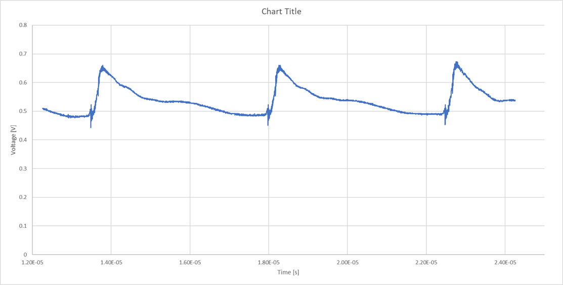
    The probe is DC coupled, I just changed the offset such that the wave is in the screen. I also provided an excel file with the raw values, if I make a chart with this data I get the following:

  • Hi Youhao,

    I have redone the test, with 12.1V input voltage, just 1 channel and a single 2.26k resistor on IOUT. I have plots for an ISET voltage of 0.5V, 1V, 1.5V and 2V, see below.

    Plot 1, IOUT voltage; (ISET = 0.5V, VOUT = 110mV):

    Plot 2, IOUT voltage; (ISET = 1V, VOUT = 215mV):

    Plot 3, IOUT voltage; (ISET = 1.5V, VOUT = 315mV):

    Plot 4, IOUT voltage; (ISET = 2V, VOUT = 415mV):

    I hope this is what you need to calculate the parasitic inductance of the sense resistor, if there is anything else you need please let me know.

    Thanks,

    Allard

  • Hi Allard,

    Youhao is out of the office and will return to the office on June 24th. He will be able to follow up on this thread at that time.

    -Garrett

  • Hi Allard,

    Is your VOUT really in the range of just a few hundred mV?  What is your load?  A constant voltage, or current, or something else?

    Thanks,

    Youhao 

  • Hi Youhao,

    Yes really, I have a resistor bank as load with a resistance of about 0.0111 ohm.

    Regards,

    Allard

  • Hi Allard,

    Not understanding your application, but the circuit should support.  Please change R59 from 68k to 100k, then you should be able to get higher load current.

    Thanks,

    Youhao