This thread has been locked.

If you have a related question, please click the "Ask a related question" button in the top right corner. The newly created question will be automatically linked to this question.

SM72295: SM72295 IC failing after two days of installation .

Part Number: SM72295
Other Parts Discussed in Thread: CSD18532Q5B, TIDA-00120

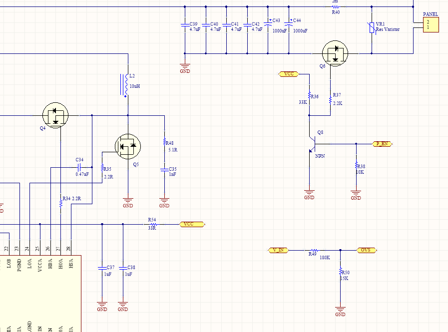
I had design solar charge controller in street light using SM72295 . the design is working good for two to three days . after that Internal driver of SM71195 getting damaged.

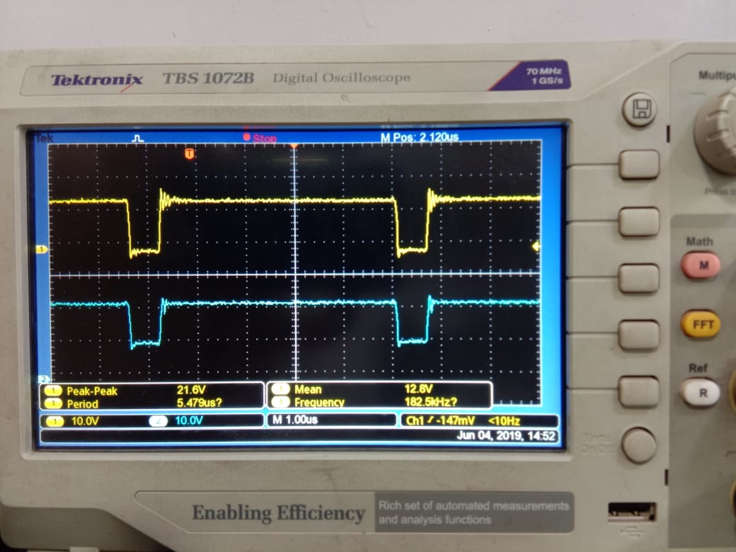
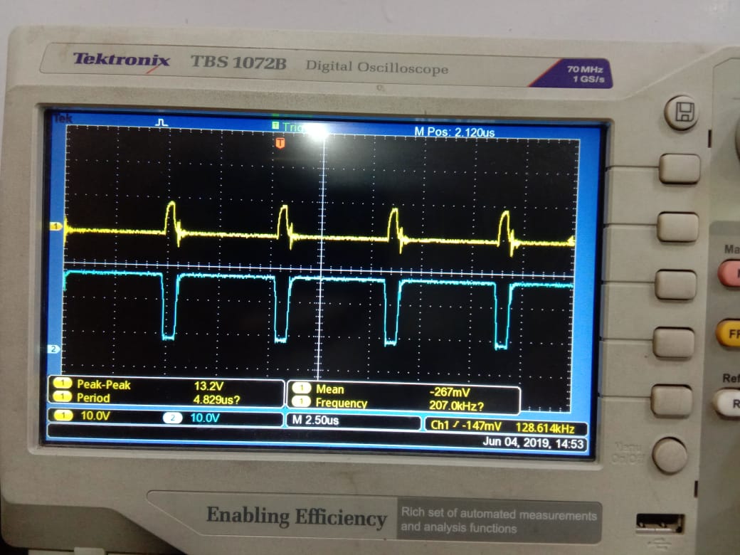
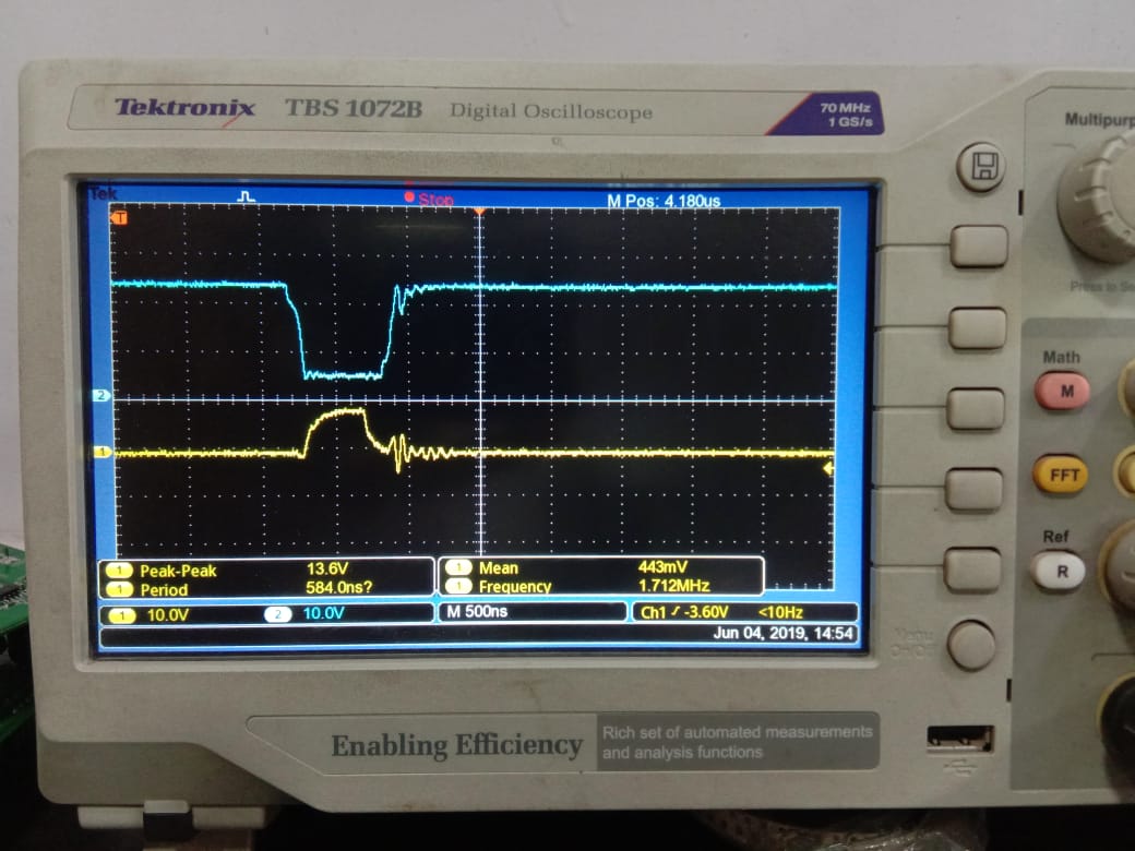
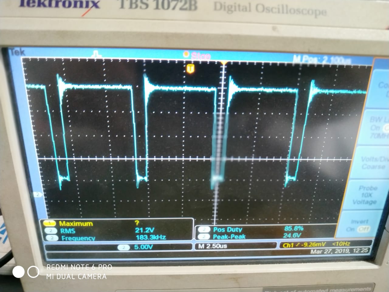
after investigating on CRO i am able to see distorted wave form as mentioned below pics.
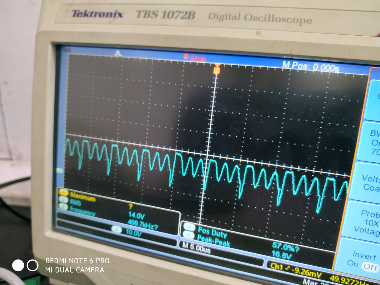
before damaged :

while testing thru multi meter i found shorting between HOA (Pin 27) and HSA (Pin 28).

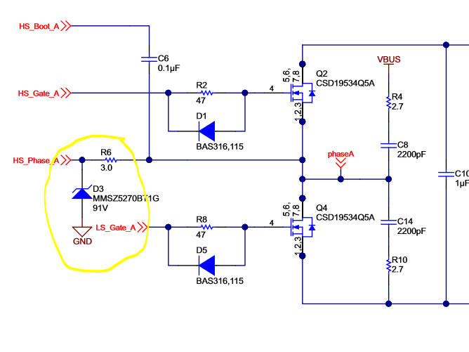
for driver protection can i use zener diode as i found in EVM , if yes then how to calculate the value of zener diode ?

Design Specification :

Panel Voltage mini/ max. : 15/24 V

Battery with BMS : lipo4 12.8 V/30Ah BMS rating (5A)

Charging Current : 5 A Max.

I am Driving SM72295 driver at 8.7V

  • Hi Mitesh,

    thanks for posting on SM72295!
    I see this looks similar to a previous issue you posted below.
    e2e.ti.com/.../788113

    It looks like the HB high-side supply is not getting charged by the VCCA cap during high-side turn on. But you also mentioned that the driver was working for a few days without issue. If the HOA output was shorted the HOA-HSA waveform should stay flat at 0V. Since there is not any max voltages being exceeded on the output you may not need zener clamp and only need to tune your gate drive capacitance. The bootstrap cap looks to be correct as recommended in the previous e2e post. I see the VCCA cap in this sch is 2x1uF. Can you confirm this is correct? The VCCA cap should be 1X1uF. Does changing this cap help solve the problem waveform you are seeing? is the same or similar issue happening on HOB? please let me know if this helps solve your issue.

    Thanks,

  • Yes i am using 2X1uF cap.1 cap is for VCCA and second is for VCCB . and I am Using Only HOA.

    I am using HOA and LOA for charging and LOB is for LED mosfet driver. HOB i am not using .

  • Hi Mitesh,

    thanks for your update,
    VCCB and VCCA are separate pins so you must be shorting VCCA and VCCB? is the VCC cap and HB-HS cap placed close to SM7225?
    Its possible that HB-HS cap is not being charged properly, can you scope the HB-HS waveform to see that its being recharged every switching cycle?
    Also, can you replace SM72295 with a new one and test everything out with a 50% duty-cycle (probe HOA-GND LOA-GND and HSA-GND waveforms) to see if the low-side is bringing the switch-node to ground in time to create the recharge path needed to charge back up the HB-HS bootstrap cap.
    is the HOA and HSA output still shorted after you remove the part?
    Is Q4 also damaged? does it ever get hot?
    what load current is being used?
    what FET are you using?
    I notice that C6 in the top sch is 100nF however C34 in the bottom sch is 470nF. Which value cap are you testing with? it should be 470nF. Also the gate resistor value differs between the top and bottom sch, what value gate resistor are you testing with?
     
    thanks,

  • Hello sir,

    Thanks for you update,

    I am Using single DC DC converter for both VCCA and VCCB .

    Both cap Vcc cap and HB-HS cap are placed close to SM72295.

    Please find waveform across HB-HS with respect to ground.

    Please find  HOA-GND  & LOA-GND waveforms below :

    After remove the part HOA and HSA output is open.

    Q4 is neither getting damaged nor heated.
    Load current is 1.2A  and charging current is 4A
    FET i am using : STP150n01f7

  • Hi Mitesh,

    Thanks for your update,

    The waveforms you shared look normal to me and the fact that the HO output is normally open after the part is removed may mean the SM72295 is not damaged at all.

    I see that STP150N10F7 which has about triple the gate charge (120nC) compared to the TIDA-00120 which uses CSD18532Q5B and recommends 470nF bootcap for a 40nC gate capactiance. Typically the bootstrap cap needs to be 10X the gate cap and the VCC cap needs to be 10X the boot cap in order for the bootstrap cap to remain replenished during normal operation. Does changing the bootstrap cap value to 1.2uF and adding a 10uF cap to VCC help with this issue?

    how long of operation does it take for the waveform to develop an issue?

    what schematic component values are you using in your testing? the top or bottom sch?

    thanks,

  • Hello sir,

    SM72295 is getting damaged , I mean to say that after remove part (SM72295) these pins are open . there is no short circuit.

    Also i had tuned the value of cap , but still got the same problem.

    And it takes 3 to 5 days to create issue.

  • Hi Mitesh,

    how is SM72295 damaged? HO and HS pins are normally open when not powered/on the board. A short circuit when the part is not powered would typically mean the part is damaged.

    did you tune the value of the bootcap to 1.2uF as well as VCC cap of 10uF and check to see if the issue remains after 3-5days?

    which sch are using? can you send me the full sch with the correct values you are testing with?

    are you testing with 47ohm gate resistors like in the top sch? if so try making these 2.2ohm.

    is there any switching cycles being missed by the controller or driver during any given time period? if there are any cycles missed where LO doesnt turn on to allow the bootstrap to charge the bootstrap voltage could not continuously replenishing itself. Can you probe HB with respect to HS (the bootstrap cap voltage) over a long period of time to see if the HB-HS voltage starts to sag or if there are any missing switching cycles?

    what reason are you using  STP150N10F7  rather than CSD18532Q5B?

    thanks,

  • Hello sir,

    Yes HO and HS pin are short circuit when the part is not powered .

    I tune the value of the boot cap 1uF and VCCA cap to 10uF. waiting for response.

    Yes i am using 2.2 ohm gate resister .

    No switching cycle is missing.

    I am using STP150n10F7 because of availability .

    Please find the schematic below .2553.TI_MPPT_SSL.pdf

  • Hi Mitesh,

    thanks for your update,

    I will wait for your response after testing the tuned cap.

    Is LOB acting the same way as HOA is acting during the issue? if so both C37/C38 may need to be 10uF. You then can add a 1 uF cap at the pin for noise filtering if need be.

    thanks,

  • Hello sir,

    Thanks for your response.

    Both LOA and LOB is OK. not getting damaged. while HOA getting issue , LOA has not continuous wave form. because of charging disconnect, so i don,t find any problem in LOA and LOB.

    I already tuned both cap . I will shared you response soon.

  • Hello Mitesh, 

    We have not heard from you, we must therefore assume that you've resolved the issue. If so, please share the resolution for other e2e users to learn from. 

    If you're still having trouble, please let us know by simply posting on this thread.

    Thanks.

    Regards,

    -Mamadou