Hello to all, this is a related post. ( )
)
I've reduced the output current so now i need 2.3A on 12.6V rail and 1.6A on 12.6V rail. That's why i've switched to TPS54360B but still have problems with the determining component values.
Of course first i've used Webench Tool and realise compensation components and switching frequency resistor values are different from my calculations and Excel Calculator Tool. I mean they are vastly different not even close. My calculations (according to formulas on datasheet) match with the Excel Sheet.
Here is Webench Circuit. Here are the changes that i want to do;
Increase input cap to 2x10uF ( 16,25uF derated) (Total ESR= 1 mili Ohm)
Increase inductor to 3,3uH (DCR= 8,6 mili Ohm)
Increase out cap to 6x10uF (ceramic) ( 51,7uF derated) ( Total ESR= 0,8 mili Ohm)

1)Should i change the compensation values as well? And if i should, how can i calculate them? Again Webench calculations and Excel calculations do not match.
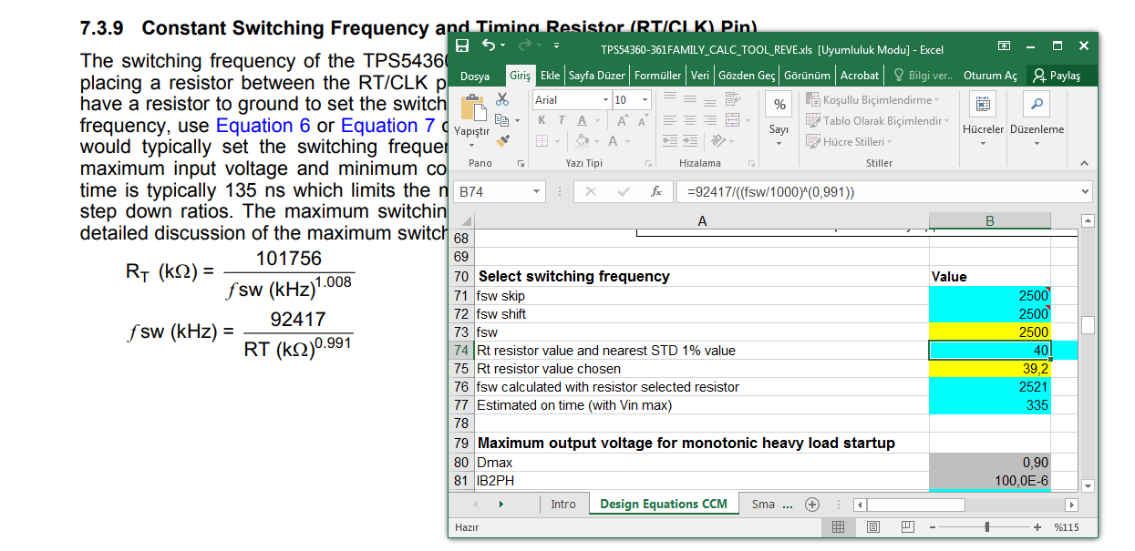
2)And of course Fsw. I need to know resistor value for 2.5MHz
Thank you advance and please keep in mind that i will use the same circuit in Inverting Topology.