This thread has been locked.

If you have a related question, please click the "Ask a related question" button in the top right corner. The newly created question will be automatically linked to this question.

TPS7A33: Why does output of TPS7A33 rise to 1.25V above 0 then drop to regulated -12V?

Part Number: TPS7A33
Other Parts Discussed in Thread: TPS7A47

Hi team,

I am posting this question on behalf of my customer. I will send the schematic internally once the question is assigned. Scope capture is attached. Thank you so much!

"I’m having a problem with a negative linear regulator (TPS7A33).  I’ve attached the power supply schematic to this page, as well as a picture of the scope capture.


Basically, when the linear regulator is enabled, the output of the regulator goes above 0V to around +1.25V before dropping to its regulated voltage of =12V.  This is causing my op amp outputs to glitch when power is applied (the +12V rail behaves as expected, with a monotonic rise to +12V).


One thing I forgot to mention is to ignore the “fuzziness” of the yellow trace on the scope plot.  I was trying to hold 3 scope probes in one hand while using another piece of equipment to trigger the event.  The yellow probe had no ground connector on it (the others did).

Can you explain the following:


1)      Why the voltage goes up above +0V before going down?

2)      How to prevent the -12V linear output from doing this.

3)      Why the +12V regulator has a much faster turn on time compared to the -12V regulator, even with the same soft-start capacitor value of 1uF?"

  • Hi Lauren,

    The temporary positive output voltage on the negative rail is likely caused by leakage paths in your load between the loads positive and negative rails.  You can prevent this by having your positive and negative rails startup together.

    Most likely your positive regulator has a different soft start equation than the TPS7A33; therefore, the same softsart capacitor would not yield the same startup time.  Please be sure to check the startup equation for your positive regulator.

    Very Respectfully,

    Ryan

  • Hi Ryan,

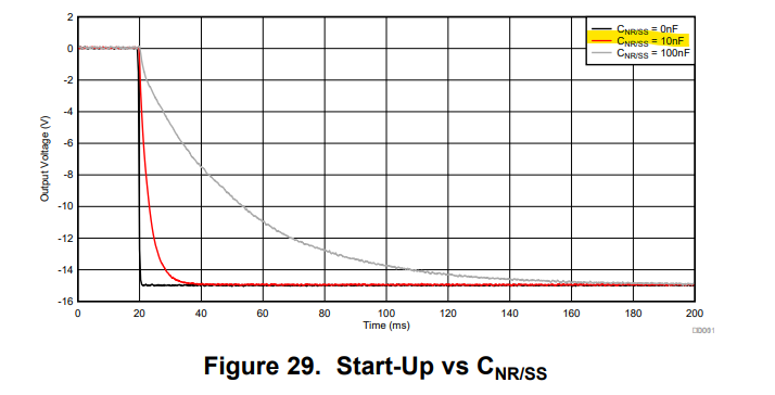
    With the recommended 1uF capacitor for the programmable soft-start, the datasheet shows about 40mS turn on time, and that's not what I'm seeing at all for the negative regulator (the positive regulator though tracks very well with what the datasheet startup graph shows).  I'm seeing about 1 second (scope plot attached).  The output load of the -ve regulator (192mA) is similarly loaded to the +ve regulator (240mA) on startup.  The output capacitance is also the same on both rails.

    What would cause the -ve regulator to have such a slow startup then?

    Thanks for the help!

    Ron

  • Here is the schematic (pdf).Power - Analog.pdf

  • Hi Ron,

    Please note that the softstart equation for TPS7A47 and TPS7A33 are different as the two regulators have different topologies.  For TPS7A33, with a 1 uF softstart capacitor you should see a startup time of 1.2 s.

    For a startup time of ~ 40 ms you will want to use a Cnr/ss on the order of 10 nF.

    Very Respectfully,

    Ryan

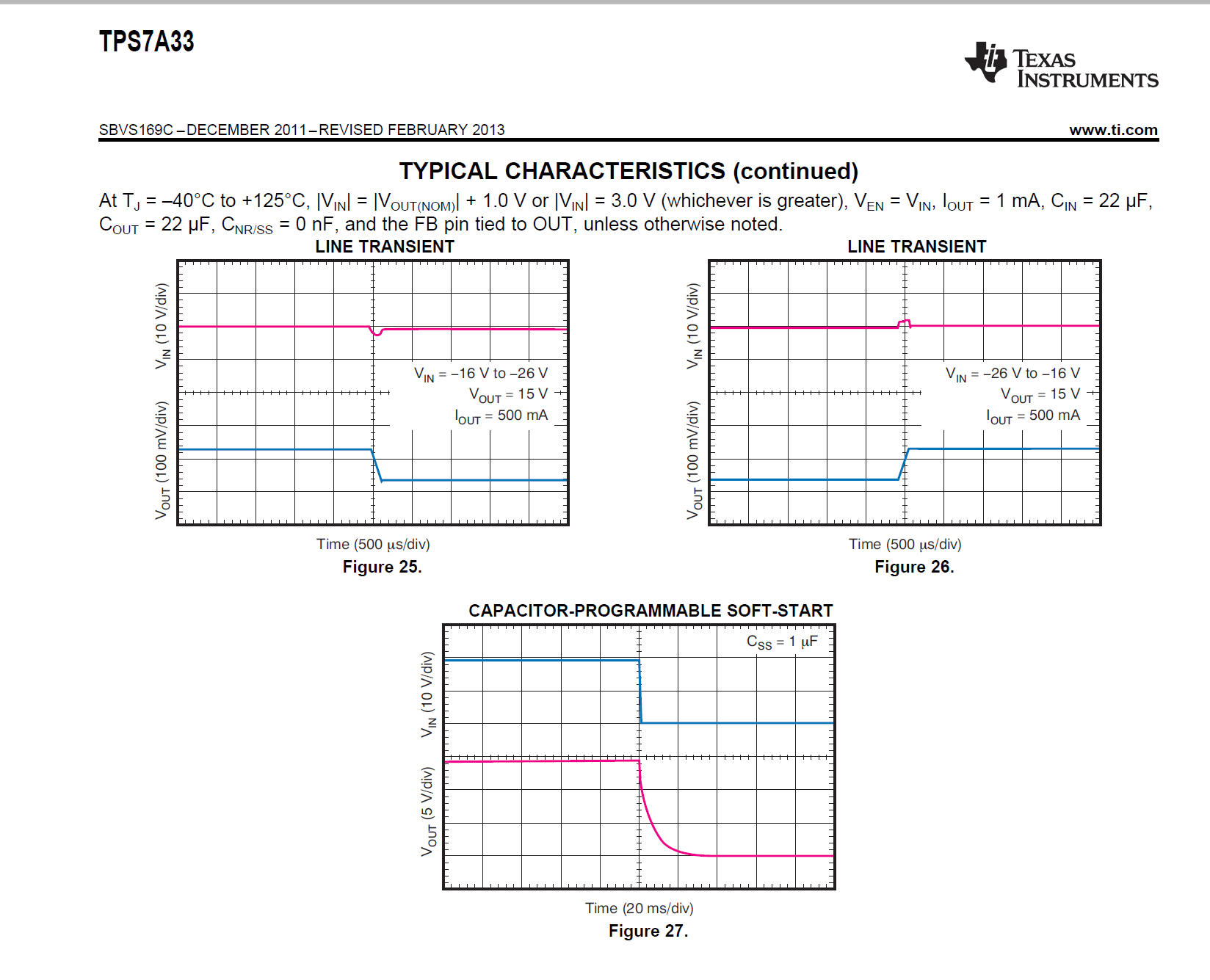
  • I looked at the datasheet and figure 27 shows a 30ms startup time with a 1 uF capacitor (which is way different from what you have in your chart).  I'll try the smaller capacitor and see how it goes.

    Ron

  • Hi Ron,

    It is important to make sure that you are using the latest datasheet revision as found on ti.com.  Please note that a typo was found in Figure 27 and corrected to show that Css = 10 nF in the current revision released April 2015.

    Very Respectfully,

    Ryan