This thread has been locked.

If you have a related question, please click the "Ask a related question" button in the top right corner. The newly created question will be automatically linked to this question.

BQ25886: BQ25886 Enters Error Reporting Mode

Part Number: BQ25886

I had some trouble.When I connected the ILIM pin to GND, the module entered the wrong mode. STAT started flickering at 1Hz. How to deal with this situation? Or can we only change modules?

Another question is, what is the battery's full state? Is STAT higher than the 8.4V set?

  • Hi,

    Can you describe your test setup and test conditions? For example, are you using an EVM or your own circuit? What is your adapter's voltage and current capability, and what kind of battery are you using? Is there any system load connected?

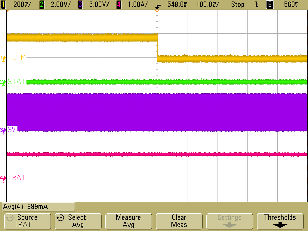
    Grounding the ILIM pin should set the input current limit to the maximum. I tried shorting ILIM to GND on an EVM, and it did not cause STAT to blink. Charging was not interrupted, as shown in the waveform below. I also didn't have any issues powering up the device with ILIM grounded. The converter starts up and charging begins.

    Regarding your other question, the battery is fully charged when VBAT reaches VREG. When the battery is fully charged, the STAT pin goes high to indicate that charging is complete. The STAT pin's logic high voltage depends on the pull-up network you use, but please keep in mind that the absolute maximum voltage rating for STAT is 6 V. Your pull-up network must not cause STAT to exceed this voltage.

    Best regards,

    Angelo

  • Thank you very much. I solved my problem because my data line was broken and the output current was limited.

    Now I have a new question,  I want to know what role D7 plays in this schematic diagram.

  • Hi,

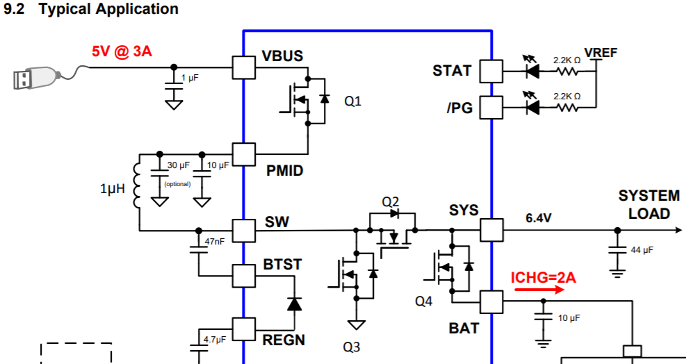
    D7 allows current to flow from BAT to SYS. It performs the same role as the body diode of Q4 shown below. Depending on your application, it's probably fine to leave this diode out.

    Please take a look at this thread as well, which discusses the same question:

    https://e2e.ti.com/support/power-management/f/196/p/779731/2884142

    Best regards,

    Angelo

  • Hi,

    I had a problem with the OTG boot. I connect the BQ25886EVM to my system motherboard and battery, and the VBUS port is connected to the TYPE-C interface.

    Now, when the system boots, an OTG line and a U disk are connected to the TYPE-C interface. When I try to pull up EN_OTG to enable it, I find that I can't output 5V and enter the BQ25886EVM alarm mode. I want to ask for your help.

  • Hi,

    Please verify that the following conditions given in Section 8.3.5 in the datasheet are true. These conditions must be met in order for OTG to start:

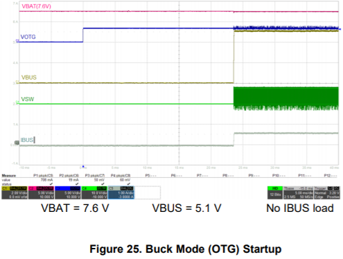
    If you think you've met all the conditions, but OTG still isn't working, then please capture a waveform with VBUS, VBAT, VOTG, and VSW, similar to Figure 25 in the datasheet:

    Best regards,

    Angelo

  •  hello, I'm here again.

    This time I would like to ask what is the function of the separation of the two places, can they be connected together? What is the impact of using the same place?

  • Hi,

    The reason for using two separate GNDs is noise reduction. PGND (power GND) is a noisier plane than AGND (analog ground), so some sensitive pins (such as TS, ILIM, and ICHGSET) use AGND instead of PGND on the EVM. AGND and PGND can be connected together using the thermal pad, as described below:

    Best regards,

    Angelo